Avoid turbulence in your compressed air system
Turbulent flow can often lead to significant and continuing energy dollar waste. It can affect productivity, quality and production equipment integrity. It’s not something you should want.
The basic rule for compressed air piping between the supply and users has always seemed clear:
- Pipe the air to filters, dryers, receivers and regulators and on to the production floor at the correct flow at the correct pressure with minimum pressure loss
- Size the outlet pipe from the compressor to meet the volumetric flow, not to match the size of the compressor discharge port
Plant engineers and operators should be aware that these principles are often overlooked. Most realize that pressure drop is directly proportional to volumetric flow and inversely proportional to line size.
Air system designers often overlook air velocity as a critical factor. Instead, they focus on friction-induced pressure loss. Ignoring air velocity can result in:
- Unplanned backpressure or pressure drop
- Elimination of effective storage for control operation
- Loss of a steady signal pressure for electronic controllers
Each outcome degrades energy efficiency, plant productivity, quality and production costs.
Basic causes of pressure drop
First is pressure loss by friction. Many pressure drop charts indicate the pressure loss for a certain inlet air flow at a continuous pressure. Friction between air and pipe wall causes this loss, which is usually denominated as pressure drop per 100 feet of pipe.
Similar charts express the estimated pressure loss for fittings in terms of “additional length of pipe.” When added to the length of straight pipe, the sum is called “total equivalent feet of pipe.” These charts reflect the basic calculations for pressure loss, which include:
- Air density at a given pressure and temperature
- Flow rate of the air
- Velocity at pipeline condition
- The Reynolds number
- Other factors, including a friction factor based on the size and type of pipe
These calculations and chart data give the probable minimum pressure loss. The pipe’s internal roughness and scale thickness dramatically affect its resistance to flow (friction loss). Resistance increases with time as the inner wall rusts, scales and collects dirt. This is particularly true of black iron pipe. Pressure drop is proportional to the square of velocity. A high volume intermittent demand can suffer dramatic pressure drop during peak periods. Ignoring this affects the processes the header feeds.
Training Manual.
For any given size pipe:
- For a constant pressure, the greater the flow, the greater the loss per foot of pipe.
- For a constant flow rate, the lower the inlet pressure, the greater the loss per foot of pipe.
Air velocity
The most overlooked idea in piping layout and design is air velocity. Excessive velocity can be a significant cause of backpressure, erratic control signals, turbulence and other losses. The British Compressed Air Society suggests that a flow velocity of 20 fps or less avoids carrying moisture and debris past drain legs. This is a reasonable limitation for main headers, interconnecting piping and main branches. Other experts feel that the maximum velocity should be 30 fps or less in branch lines shorter than 50 feet in length. Determining air velocity is easy.
Values for Di as a function of pipe schedule are tabulated in various engineering reference books. Although the formula assumes isobaric flow, it’s usually adequate for rough evaluations. Other more complex relationships accommodate flow with pressure differentials.
So what’s wrong with high velocity?
Some argue it’s simply better for air to get there faster. This is true. But what happens when that high-speed air goes through a block valve, crossing tee or other fitting? It produces turbulence, which, in turn, produces backpressure — two factors that degrade system performance. Here are some examples.
Textile mill
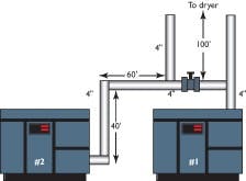
Short cycling in a 350-hp, oil-free, two-stage rotary screw compressor with two-step capacity control troubled this plant. The twin 1,500-cfm compressors were configured as shown in Figure 1. Compressor No. 2, the trim unit, was short cycling. The plant installed a blow off valve so the trim unit ran at part load with continuous blow off. This was obviously expensive because both units were at part load in demand, but at full electrical consumption. It operated like this for more than five years.
The air velocity for 1,500 cfm in a four-inch Sch 40 steel pipe at 90 psig was about 40 fps, twice the recommended value. The pressure loss in 200 ft. of four-inch pipe and one 90-degree short radius elbow was 0.89 psig — not very significant. Calculated values suggested this was an excellent piping arrangement.
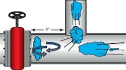
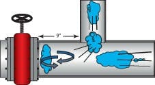
The actual measured pressure drop from the compressor discharge to the dryer inlet was eight to nine psi — quite excessive. The air running through a 90-degree turn and dead heading into the block valve located only nine in. away caused this loss (see Figure 2). The block valve allowed the compressor and dryer combination to be alternated.
The turbulence sent a pressure signal to the capacity control pressure switch sensor to unload the compressor prematurely, which caused short cycling (load four seconds, unload four seconds). It also caused backpressure, which eliminated any effective storage for the 10-psig operating band.
With six-inch pipe, the velocity would fall to about 17.8 fps and an eight-inch line would have a velocity of about 10.3 fps. Either larger pipe would eliminate most of the pressure drop.
What is the annual cost of electrical energy to produce this eight-psi drop? At a rate of $0.05 kW-h, it’s more than $9,000. During the five years, the plant spent more $45,000 to generate pressure that was never used. The control problem that caused the plant to run in blow off mode, rather than short cycle and harm the equipment, could well have wasted another $25,000 to $30,000 annually.
Aluminum mill
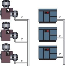
This plant had a short cycling problem in one of two compressor rooms, both of which have three 150-hp 750-cfm compressors running at 90 psig (see Figure 3).
The three lubricant-cooled rotary screw compressors ran on two-step control and were short cycling (six seconds on, six seconds off). The lack of effective blow-down and idle consumed their full kW energy draw, which also led to high maintenance and repair costs for coolers, motors and airends. On the other hand, the three reciprocating units were loading and unloading in an acceptable manner (one minute on, 30 seconds off), saving power and causing no mechanical problems.
Both systems used tees to the header (see Figure 4). The only difference was the pipe size and resultant velocities. Room 2 with the rotary units had extremely high velocities, which cause high turbulence and pressure loss at the crossing tees, bends and valves.
Plant maintenance personnel explained that the rotary units used two-inch discharge pipe because that was the size of the port. The instruction manual also advised using pipe the same size or larger.
Short cycling induced by high velocity and piping configuration forced the plant to run three 150-hp compressors when the original specifications called for only two units. At $0.05 per kW-h, this plant wasted more than $60,000 per year in energy costs for more than 20 years — $1,2000,000.
Milk and dairy processing
In this case, the plant was running four 100-hp lubricant-cooled rotary screw compressors under modulating control. It was losing productive capacity because a 20-psi pressure drop made it impossible to maintain the required minimum 90 psig in the header.
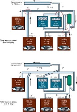
The piping schematic in Figure 5a shows the original piping and Figure 5b shows its modification. Four 100-hp 490-cfm oil-cooled rotary screw compressors delivered air to a six-inch main header. The velocity in the four-inch interconnecting piping was as follows:
- 13.2 fps @ 490 cfm.
- 26.4 fps @ 980 cfm.
- 39.6 fps @ 1,470 cfm.
- 47.4 fps @ 1,760 cfm.
Four crossing tees added turbulence at these velocities. The total pressure loss with all machines at full load was 20 psig. When demand increased, the pressure in the main fell below 90 psig, shutting down production.
Two changes solved the problem. First, the four-inch crossing tees were changed to directional angle entry. The pressure drop fell to six psi and the main system now receives 104 psig that is easily regulated to a steady 90 psig. The connections were prefabricated and installed during a one-day maintenance shutdown at a cost of $4,200. This eliminated the production interruptions that had occurred for 20 years. Second, the compressor discharge pressure was reduced to 98 psig, which represents a power saving of six percent, equivalent to about $9,585 annually.
Short cycle and surge
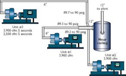
Figure 6 shows three centrifugal compressors, each of which delivered about 3,900 cfm at 90 psig at full load through a six-inch line (46.3 fps), feeding a 12-inch pipe (11,700 cfm, 35 fps). Unit No. 1 fed the end of the 12-inch header coaxially. The line from unit No. 2 entered at a 90-degree crossing tee and that from unit No. 3 entered just upstream of the No. 2 connection but through a 45-degree directional entry.
In this case, three air streams converged within a nine-inch axial length of pipe. The turbulence at this connection was reflected in the pressure oscillating between 89 to 90 psi. That’s not bad, but centrifugal compressors are sensitive to backpressure. The measured flow from units No. 1 and No. 2 was a constant 3,900 scfm. No. 3 short cycled from 3,900 to 2,900 scfm every five seconds. Full turndown on No. 3 was 3,300 scfm. Thus, we concluded that the effect of the sensed pressure spike at the compressor controller was almost equal to the 10-psig operating band. Observation showed the blow off valve also trying to move. The annual loss of about 750 cfm cost the company about $42,000, in addition to the surging and productivity problems.
Lengthening the 12-inch header and bringing each compressor in with a directional entry oriented 30 degrees and 30 inches apart solved the problem. The pressure stabilized at 90 psig with no short cycling evident. Streamlined connections handle high velocity without significant problems.
These examples clearly show a key item often overlooked is compressed air velocity. During many years of troubleshooting compressed air systems, we find these problems in the newer systems installed during the past 20 years. Rotary screw compressors seem to be supplied with smaller and smaller NPT connections, which are subsequently construed as valid guidelines.
When installing compressors, always size the pipe according to the anticipated flow. Don’t be misled by the discharge flange or pipe size. Good piping practice dictates the use of directional angle entry instead of crossing tees and long radius ells rather than short radius fittings. Also eliminate dead heads and other sources of turbulence. Using air receivers and large headers effectively can offset many potential pressure drop problems.
Hank van Ormer is president of Air Power USA Inc. Don van Ormer is the company’s vice-president. They can be reached at [email protected] or (740) 862-4112.
