When a piece of equipment needs slow input speed and high torque, it’s common to use an electric motor coupled to an industrial gear reducer to achieve the desired speed and torque. The gear reducer multiplies the output torque from the motor and reduces the motor output speed by the same ratio. There are many kinds of industrial gear reducers from which to choose. Internally, those gear reducers might use worm gears, helical gears, or bevel gears to increase torque and reduce speed. One of the most popular types of gear reducers is based upon worm gears.
Torque versus purchase price
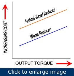
Figure 1. It’s typical for a 60:1 helical or helical-bevel reducer to have three stages of gearing compared to one stage of gearing in a worm reducer.
When one selects a gear reducer, one of the most important decision criteria is the relationship between the reducer cost and the amount of torque generated from its output shaft. Worm reducers are the leaders when it comes to the cost-versus-torque comparison. A principal factor driving cost competitiveness of worm reducers relates to the overall gear reducer ratio. The overall gear reducer ratio is the number of rotations of the input shaft that results in one rotation of the output shaft. Most worm gear reducers offer ratios of as much as 60:1 in a single stage of gearing, and a few offer even higher ratios. With only one stage of gearing, the related multiple shafts, bearings, spacers, and other hardware that would be required in a multistage reducer aren’t required. It’s typical for a 60:1 helical or helical-bevel reducer to have three stages of gearing compared to one stage of gearing in a worm reducer. The gears, bearings, and shafts are the most expensive gear reducer components. With fewer of these, worm reducers cost less than other types of gear reducers (Figure 1).
Availability and commonality
Most domestic manufacturers stock a substantial number of reducers in their warehouses. Those can be shipped on the same day the order is placed. In addition to readily available inventory, there’s also dimensional commonality on critical mounting dimensions among the major domestic worm reducer manufacturers. Those critical dimensions include the output shaft diameter and length; mounting hole size and location in the housing; output shaft height; and overall reducer housing height. The gear ratios offered also have been standardized. Some have increased the output and input torque ratings of their products through improved gear designs along with the use of high-performance materials and synthetic lubricants. Those increases in input and output torque make it possible to replace an older reducer with a new reducer from a different manufacturer. The increased ratings provide a larger service factor and longer life than the original reducer.
Mounting options and features
Figure 2. The right-angle configuration and the hollow shaft give the worm gear reducer more flexibility in application.
The worm gear in a worm reducer runs at a right angle to the input worm shaft. Because the worm gear is mounted on the output shaft, both ends are available for use. Available common output shaft configurations include single and double extended solid shafts along with hollow output shafts. The use of hollow output shafts is becoming more common in the United States, as it offers several advantages over a solid output shaft (Figure 2).
An equipment OEM can extend its drive shaft a relatively short distance and mount a hollow bore worm reducer on the extended shaft. That mounting eliminates the need for chains, belts, or other equipment to transmit torque from a solid-shaft reducer to the application. Guarding is simplified, and the maintenance normally required for chains and belts is eliminated. Several manufacturers offer a sealed-for-life reducer that doesn’t require a vent plug or oil level changes for different mounting positions. Those features allow mounting in multiple positions without the need to relocate the breather or add lubricating oil. Because of the popularity of worm reducers and the multitude of applications, they’re available in standard and food industry washdown duty packages, offer C-face inputs for standard NEMA motors, and have multiple options, such as mounting flanges and bases (Figure 3).
One aspect of worm gearing to avoid is the self-locking feature that some gear ratios might theoretically offer. Because of the many variables that affect the reducer’s ability to self-lock, most manufacturers recommend a brake motor or other means to keep the reducer from being back-driven.
Long life
Figure 3. A sealed-for-life reducer doesn’t require a vent plug or oil level changes for different mounting positions. A soup-producing plant can use this same hollow-bore unit in multiple mounting positions without the need to relocate the breather or add oil.
Industrial worm gear reducers have a hardened worm running with a worm gear of a softer material — a bronze alloy selected with wear in mind. Unlike hardened helical or bevel gear sets, a worm gear set is designed to “wear in” over time. Some people think the wearing of the worm gear results in a shorter life than other gearing types. However, the wearing of the bronze drops off substantially after the wear-in finishes. When worm gear manufacturers select a bronze material, they balance the resistance of the bronze to wear over time versus the ability to wear-in. During wear-in, the worm gear temperature temporarily increases. A softer bronze wears in more quickly with lower break-in temperatures, but it won’t last as long. A harder bronze lasts longer but generates higher break-in temperatures. A harder bronze is the best compromise between wear-in and wear-out. When properly sized to the application, worm gear reducers last at least as long as other gearing types.
Noise
All gear reducers generate noise depending on the type of gearing used, the gearing accuracy, the quality of the manufacturing processes, and product design. Worm gear reducers have multiple advantages with respect to noise. Their teeth slide into contact with each other. That sliding action avoids the abrupt tooth-to-tooth contact that occurs with helical and bevel gearing. In addition to sliding into engagement, well-designed worm reducers have more teeth in contact in the gear mesh compared to a helical or bevel reducer, which results in lower noise levels. Also, worm reducers typically have only one set of gears that produce less noise than the multiple sets in helical and bevel reducers. The fewer number of bearings also helps to keep the worm reducer noise level lower.
Overall, gear reducers with worm gears offer advantages over helical and bevel gearing. Worm gear reducers have a low cost-versus-torque ratio, and domestic models are readily available and interchangeable. The right-angle mounting of a worm gear reducer, along with the hollow output shaft and sealed-for-life options make worm-gear reducers suitable for a host of applications. Also, the long life and reduced noise from worm gearing have contributed to their popularity.
Chuck Russell is senior principal engineer at Baldor (www.baldor.com). Contact him at (864) 281-2438 or [email protected].


