Converting motors from horizontal mount to vertical mount
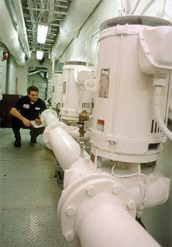
Occasionally an end user wants to take a motor designed for horizontal mounting and use it in a vertical position. (Figure 1 illustrates a horizontal motor in a vertical shaft down position.) This article addresses some of the key mechanical factors that should be considered when applying a horizontal ball-bearing motor in a vertical mounting position.
These key factors include:
- Axial thrust load capacity of bearing supporting rotor weight
- Rotor weight
- Weight of output shaft attachments
- Axial thrust from direct-connected driven equipment\
- Bearing lubrication paths
- Bearing lubricant retention
- Shaft up or shaft down orientation
- Ingress protection
- Locking axial thrust bearing
Axial thrust load capacity
The first four factors above are inter-related because the weight of the rotor and any shaft attachments result in axial load on the fixed (thrust) bearing. Direct-connected driven equipment such as impellers or fan/blower blades can also impart axial thrust load on the fixed bearing.
In most cases, the axial load capacity of the fixed bearing is well above that required to provide an acceptable expected bearing life. Bearing life is evaluated based on the L10 life of the bearing, where L10 life is the number of revolutions or hours after which 10% of a large population of identical bearings will begin to fail. It is also sometimes termed “minimum expected life.” A common L10 life is 40,000 hours, which is about 4.5 years of continuous operation.
As an example of determining axial thrust load capacity, consider a 200 hp (150 kW), 1,750 rpm, horizontal motor with a rotor weighing 800 lb (360 kg) to be supported by the 6318 drive end bearing that is fixed (axially locked) in its housing. If there is little or no radial load, the bearing life with these conditions would be in excess of 200,000 hours. The bearing life value was obtained using an online bearing-load calculator available at a number of bearing manufacturer websites.
If dealing only with axial load, a simple method can be used. The axial load capacity of a deep-groove ball bearing is 0.5 times the basic static load rating, designated C0 in bearing manufacturer data tables. The C0 rating for the 6318 bearing is about 24,000 pound-force (lbf) [107,000N], making it more than capable of handling the 800-lbf load. Note that a bearing load is a force; thus the units are pound-force (lbf) or Newton (1N = 0.225 lbf), not pound(s) or kilogram(s).
To simulate an application of the same 200 hp motor with a radial load as well as the axial load, we will consider it in a belt-drive application. In addition to the 800-lb rotor, a pulley (sheave) weighing 100 pounds is mounted on the motor shaft, resulting in a total axial force of 900 lbf. Using the load calculation method given in the Feb. 2003 EASA Currents newsletter article titled “How To Determine Bearing Load Capability And What To Do When It’s Excessive,” the radial load on the 6318 bearing is 1,960 lbf.
Using an online bearing calculator to evaluate the 1960-lbf radial load combined with the 900-lbf axial load, the estimated 6318 bearing life is about 15,000 hours. If the customer required 40,000 hours estimated life for the motor bearings, the motor is not suitable for the vertical application. If the motor was subjected to only the radial load of 1960 lbf, the estimated life would be about 41,000 hours and would meet the 40,000 hours minimum requirement.
Caution: Some online calculators have preset conditions that are not displayed. The most significant condition that is often not displayed and therefore not modifiable is the bearing internal radial clearance. For example, the online calculators of FAG, NSK, and NTN appear to use a normal (sometimes termed C0) internal radial clearance. However, the SKF online calculator allows the user to select the internal radial clearance. If the normal internal radial clearance is selected with the SKF calculator, the bearing life results of all four of these calculators are within 10% of the average. Had the C3 internal radial clearance been selected for the SKF bearing, the life estimate would have been about 75% greater than the average.
Bearing lubrication paths and retention; shaft orientation
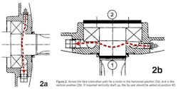
The next key factor is bearing lubrication paths. Figure 2 illustrates an across the face lubrication path for a motor in the horizontal position (2a), and in the vertical position (2b).
If the motor is oriented vertically with the shaft end up, the grease entering the lubricant chamber of the drive end bearing in Figure 2 will tend to go through the bearing and leak into the interior of the motor. If that occurs, only a small amount of grease will reach the grease relief that should be opened during the relubrication process. The scenario that could occur is that the person lubricating the bearing will add more grease until lubricant is observed exiting the relief port. The consequence is overlubrication of the bearing and a probable reduction in bearing life. To prevent leakage a lip seal can be added below the bearing at position #2 in Figure 2b.
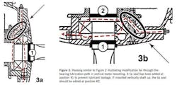
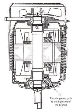
If the motor is oriented vertically with the shaft end down, the grease entering the lubricant chamber of the drive end bearing in Figure 2 will tend to go through the chamber and not reach the bearing. This scenario is further assured as the person relubricating the bearing probably will cease adding lubricant when grease is observed exiting the relief port. Modifying the housing to convert from “across the face” to “through the bearing” as illustrated in Figure 3 will provide a more-positive lubrication path for the drive end bearing. The modification is done by drilling a hole at about a 45-degree angle as shown in the circled section of Figure 3. This allows the lubricant to enter the chamber on the inboard side of the bearing, thus providing a lubricant route through the bearing. Note: The grease should enter above the bearing and discharge below the bearing.
The lubrication path of the opposite drive end bearing also needs to be addressed. If the motor orientation is vertical shaft end up, the opposite drive end bearing is the lower bearing, and its housing can be modified the same as was done for the drive end bearing with the shaft down orientation. Similarly, if the motor orientation is vertical shaft end down, the opposite drive end bearing is the upper bearing and its housing can be modified the same as was done for the drive end bearing with the shaft up orientation.
Ingress protection
If the motor is vertical shaft up or has an upper shaft extension such as for an external cooling fan, a lip seal should be installed at location #1 as shown in Figure 4. That will help prevent external contaminants from entering the upper bearing lubrication chamber. Note: For optimum seal life size the seal for a shaft diameter should be 0.020” (0.5 mm) larger than the actual shaft diameter.
If there is a shaft extension at the lower end of the motor, adding a lip seal as shown at location #3 in Figure 4 will aid in retaining lubricant in the lower bearing and its lubricant chamber. Similarly, adding a lip seal as shown at location #2 below the upper bearing will aid in retaining lubricant in the upper bearing and its lubricant chamber.
A drip cover may be added to a drip-proof motor that is mounted shaft down to provide additional protection against entry of liquids such as water. Figure 1 illustrates a drip-proof horizontal motor mounted vertically shaft down and with a drip cover.
Locking axial thrust bearing
The fixed bearing in the horizontal position is usually the drive end bearing and is locked axially by the outer race housing on the outboard side and the inner back cap. If the motor is to be mounted with a shaft down orientation, no additional axial locking steps are necessary. Further, if the inner race is axially locked to the shaft by a locknut or snap ring, no additional steps are necessary when mounting the motor in a vertical shaft up or shaft down orientation.
If the inner race of the fixed bearing is not axially locked to the shaft, a locknut or snap ring will need to be added. If the motor is direct-coupled to the driven equipment, the outboard shaft adjacent to the bearing can be threaded to accept the appropriate size locknut and lockwasher. Or, an appropriate-size groove can be machined into the outboard shaft adjacent to the bearing to accept the applicable-size snap ring. Modify the shaft for a bearing locknut and washer for applications with relatively high radial load such as belt or sprocket/gear drives. Snap rings should not be used in relatively high radial load applications.
About the Author
Thomas Bishop
EASA
Tom Bishop, P.E., is a senior technical support specialist with the Electrical Apparatus Service Association and has more than 30 years of hands-on and engineering experience at electrical machinery manufacturing and apparatus service firms. Bishop has authored dozens of technical articles and papers and presented numerous seminars on electric motor application, maintenance, and repair. In addition, he is chairman of EASA’s Technical Services Committee and a principal member of the National Fire Protection Association Electrical Equipment Maintenance Committee (NFPA 70B). Contact him at [email protected].
