8 good design practices for PLC systems
PLCs (programmable logic controllers) are found everywhere in industry today. Proper PLC system design can provide many years of service for a machine or process and greatly improve efficiency and profitability for the owner.
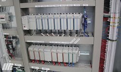
Why do we use a PLC? PLCs can be “relay replacers,” providing logic, timing, and counting capabilities that would be difficult to do with discrete components (see Figure 1). PLCs can perform math functions, making calculations based on external signals and/or HMI (human-machine interface) input. A good example of PLC use is with VFDs (variable frequency drives). PLCs can now be networked to many VFDs via Ethernet/IP or other fieldbus type communications protocols. By using the communications protocol, a great deal of wiring can be eliminated.
Before we apply a PLC to a machine or process, let’s look at some design and maintenance practices that are critical to a successful implementation.
Safety
Before we embark on a PLC application to a machine or process, a safety review must be performed. The first step is a hazard and operability analysis (HAZOP) of the machine/process. Once the HAZOP is completed, safety devices are applied to eliminate or reduce the hazard. Safety issues can include guarding, light curtains, operator safety, protection from falling hazards, electrical shock, or thermal issues (burns, open flames).
Some manufacturers offer safety PLCs, which have special safety-related functions integral to the device. It is recommended to use safety relays for emergency stop circuits, light curtains, safety mats, guarding devices, and interlocking switches. Safety relays use a dual-channel approach and provide higher levels of safety. They cannot be easily defeated.
Safety functions can be quite involved, and many firms will perform a safety audit for you.
Grounding
Grounding is a huge topic, but some basics must be heeded. Poor grounding has caused many problems in industrial control systems. Every good panel design should have a single point to attach the system ground. It is typical practice to use a ground lug and/or a ground bar. Scrape the paint off the subpanel where you are attaching the ground lug and ground bar. Make sure that all devices are grounded per the manufacturer’s recommendations.
Environmental concerns (heat / cold / surges)
PLCs must be protected from heat, extreme cold, and electrical surges. Make sure you read the specifications for the PLC and associated modules. Cooling devices such as fans, air conditioners, coolers, and pneumatic coolers can be applied to keep the enclosure interior at a desired temperature. For outdoor or cold environments, consider having panel heaters installed. Make sure that cooling or heating devices have thermostats to prevent runaway conditions and to save energy.
It is recommended to use surge suppression devices to protect against external surges such as lightning and utility switching disturbances as well as internal surges caused by the plant’s electrical equipment.
Electrical design strategy
First, always use a master control relay (MCR). This latching relay circuit energizes when all emergency stop pushbuttons and other safety devices are satisfied, and the user presses a control start pushbutton. Typically, a control stop push button in the circuit can also de-energize the MCR.
Additional contacts on the MCR supply control power to the PLC output modules. Therefore, when an emergency stop condition arises, the MCR de-energizes and output power to the PLC is dropped.
Caution! Remember that safety must be the prime consideration in the PLC design. Always ask yourself, “Will de-energizing any output in an emergency stop condition cause a hazardous situation?”
Some designers like to use the MCR to disable PLC input circuits as well. Other designers do not do this, as they may want the PLC to be aware of all input conditions regardless of what the emergency stop circuit and MCR circuit are doing. Again, safety comes first.
Though the MCR is key to design strategy, below are some other important considerations.
Control voltage: 24Vdc is becoming the de facto standard for control voltages, although 120Vac is still very common.
Physical layout: PLC manufacturers have guidelines for mounting the device. Always ensure that you have left adequate space around the PLC for airflow. It is also a good idea to leave three to four inches below the PLC device or chassis for wiring. If mounting a PLC that does not have a fixed chassis, leave extra DIN rail space to the right of the last I/O module for future expansion. Don’t paint yourself into a corner, space-wise.
Always use good panel-building practices. Use stranded machine tool wire (MTW) and use properly sized wire. Typically, #18 AWG (American Wire Gauge) stranded MTW conductors are used for PLC inputs and outputs. Prewired terminal modules are also available from PLC manufacturers to facilitate quick field wiring.
Make sure that all terminal blocks are marked with the wire number.
Follow the manufacturer’s recommendations and read the specifications carefully when choosing wiring for the PLC. Be sure to use the proper color codes for wiring. Blue is typically for DC, red for 120Vac hot, white for 120Vac neutral. Some engineers like to use other colors to denote PLC inputs and outputs; this is fine as long as you are consistent. Some designers have used gray wire for inputs and orange wire for outputs. Never use yellow for any wire except wiring coming from another panel that may be energized. If in doubt, check the Underwriters Laboratory (UL) 508A, Joint Industrial Council (JIC), and National Fire Protection Association (NFPA) 79 standards.
Separation of different voltage levels: Good panel design keeps higher voltage power devices away from control signals and analog signals. Typically, designers tend to place the 460V or 230V devices at the top of the subpanel and to the left. The PLC and control components are usually located near the bottom and to the right. There are many ways to layout a panel; use common sense. The UL 508A standard is a good source of information regarding the separation of conductors and isolation. If power and signal wires must be near each other, make sure they cross at right angles.
PLC digital outputs typically can handle 1 or 2 amps at most. For driving solenoid valves or other loads, it is recommended to use interposing relays.
Analog I/O concerns: Analog inputs and outputs are prone to noise issues. As the current signal is less likely to be affected by noise, 4–20mA signals are commonly used for analog circuits. Use good quality shielded cable; shielding and grounding techniques are well beyond the scope of this article, but make sure to follow the manufacturer’s recommendations for wiring practices.
I/O count and spares: This is a very important topic. A good rule of thumb is to have 20% spare I/O in a system. Unless you are installing a very simple “brick” type PLC, account for spare slots and spare I/O for your system. Always wire every PLC input and output to a terminal block, even if they are spares. This is a good practice and makes future additions to the system much easier to implement.
Networking: Many modern PLC systems communicate with Ethernet or some other fieldbus. If using Ethernet, provide a good quality industrial Ethernet switch such as Cat. 6, and use shielded Ethernet cables. Many systems use a 120Vac outlet and Ethernet interface device on the front door of the electrical enclosure. These devices can be ordered with a single or duplex 120Vac outlet and an Ethernet port. When performing maintenance on the system, you can plug in a laptop and you don’t have to look for a nearby outlet. Further, it maintains arc flash integrity of the enclosure, as the door need not be opened.
Make sure that the network IP addresses, subnet mask, and gateway are all documented.
Electrical schematic documentation
A good PLC design must include proper PLC documentation. Create a PLC overview drawing—this sheet shows the complete PLC chassis, with all modules in an overview format. This drawing should show the part numbers of each module, slot numbers, and which wire numbers pertain to each module. Also, be sure to include a reference for the sheet number(s) that contain each module’s schematics.
A networking sheet is required that must show each device on the network with its part number and associated IP address. Make sure to include the subnet mask and gateway address. This drawing should show a suggested programming laptop IP address, to prevent any conflicts.
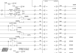
The electrical schematic for each module can be on its own sheet, although most times, designers tend to put two modules of the same type on one sheet. It depends on the size of the system. Make sure to identify the PLC module with a part number and slot number. Reference all wires to their origin and their destinations on other sheets.
The documentation shows wire numbers, PLC input and output numbers, and connection points for the input and output devices. Figure 2 shows all the parts of documenting the drawing properly.
Programming considerations
Programming a PLC is well beyond the scope of this article; however, there are some things to remember. Ensure that the programmer documents the PLC program so that people servicing the machine or making future alterations can see what the program is doing.
You must always understand how your machine or process works and ensure that the program is written clearly and can be understood by your maintenance personnel. What alarms are needed? What happens during abnormal events? How do you shut down the process safely?
It is good to print out a paper copy of the PLC logic and keep it handy for future reference. This can be a great troubleshooting aid if the maintenance person does not have the software to view the PLC program. Always document any changes to the electrical schematics and the PLC logic.
Make sure that you have electronic copies of the PLC program stored in a secure location. If the process or machine is ultra-critical, consider storing in more than one place, including off-site.
Finally, document any equipment upgrades. Not doing so risks maintenance personnel trying to repair a machine, only to find that the wiring or program has been changed and the update was not documented.
Use an HMI
HMIs are very inexpensive, and they give you a nice window into the PLC operation. Many firms struggle because they do not have the programming ability or the software for the PLC. With an HMI, you can adjust timer and counter settings, see the status of internal bits and values, set analog values, and do many more things. Passwords can be used to keep operators out of sensitive areas.
Maintenance
Always keep electrical panels free of dust, dirt, and other debris. Make sure that wiring is kept neat and wire duct covers are kept in place. Periodically, all screw terminals should be inspected and tightened. Do not overtighten the terminals; snug is good, but overtightening can make things worse. If in doubt, follow the manufacturer’s recommendation for a torque setting.
Make sure the panel is labeled with the networking IP addresses, fuse ratings, the PLC program file’s name, and anything that makes it easy to service the machine.
In summary
We have barely scratched the surface of PLC system designs in this high-level overview; however, keep the following points in mind for system optimization:
- safety
- good grounding practices
- environmental concerns
- design strategy
- electrical schematic and PLC logic documentation
- programming considerations
- HMI usage
- maintenance factors
Following the tips above will arm you with helpful information whether you are the system designer or working with a qualified in-house or third-party specialist. Implementation will also help you realize many years of service from your PLC system.


