With the growing adoption of the industrial internet of things (IIoT) and the ability to seamlessly transmit and share supervisory and control data, industrial Ethernet networks have become an increasingly vital asset on the plant floor. They are critical to monitoring and controlling industrial machines and field devices at the I/O level such as relays, electronic flow meters, remote telemetry units (RTUs), and programmable logic controllers (PLCs), while also collecting and transmitting vital manufacturing and production information across operational technology (OT) and information technology (IT) networks for real-time analysis and improved productivity.
All networks constantly undergo changes as new devices and equipment are brought online and spaces are reconfigured, but the plant environment can be especially fluid. Not only do plant managers and OT staff need to consistently ensure that their network infrastructure can support the signaling requirements of new machines and applications, but ongoing changes to the network and demanding industrial environments can also increase the potential for problems. Given the importance of ensuring industrial Ethernet network performance, reliability, and uptime to avoid costly unplanned downtime and keep machines online and in production, a key aspect of effective plant network management is the ability to qualify network performance and locate and identify any problems as quickly and easily as possible.
Qualifying network performance for new equipment
While the plant network was likely tested when it was first deployed, production machinery is constantly being upgraded or new equipment is being added to keep up with manufacturing demands. For the network to support a given application, it needs to comply with industry standards and meet all required specifications for that application. For example, while initial equipment running a Profinet 100 megabits per second (Mb/s) application may have been adequately supported by a lower performing network cable, upgrading the equipment may now require that the network has the bandwidth and transmission capability to support an EtherCAT 1 gigabit per second (Gb/s) application.
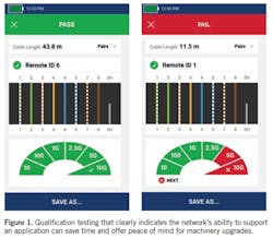
Before adding new equipment and risking not being able to bring it online quickly, plant managers can save time and headache by conducting a qualification test that can show the capability of the network infrastructure to support the new equipment. Qualification testing can be easily done with a tester designed to support common industrial Ethernet protocols across a range of bandwidth needs (see Figure 1). These testers look at performance parameters like insertion loss, return loss, near end crosstalk (NEXT), and delay skew and compare them to the limits specified by industry standards for a given application to clearly indicate pass/fail status.
It’s important to note while some simple testers will indicate continuity and the ability to transmit data across the link, they won’t necessarily determine the infrastructure’s ability to support a specific application. A true qualification tester uses specific standards-based measurements to test the cable across a range of frequencies based on the actual application it needs to support. Additionally, throughout a plant floor, equipment is often connected to the industrial Ethernet network via a variety of connector interfaces, such as industrial-grade RJ-45 or M-series connectors like the 4-pin D-coded M12, 8-pin X-coded M12, or the smaller M8 connector often used for industrial sensors. Having a qualification tester that supports multiple commonly used connector industrial Ethernet interfaces can significantly ease testing.
Verifying connectivity when problems arise
More than half of industrial Ethernet network problems on the plant floor are related to the cabling. Frequent moves, adds, and changes in these environments increase the chance for improper terminations. Network cables and connectors also have a greater potential for damage in demanding plant environments where they are more likely to be subject to vibration, crushing, cutting, abrasion, and contamination.
The first step in troubleshooting the network is to verify connectivity. If cables have been damaged somewhere along the link or if each conductor of the cable is not correctly connected to its corresponding pin at the termination point, it can prevent the signal from reaching the other end. Verifying connectivity can be achieved with a simple wiremap test that looks for opens, shorts, and miswirings. Opens occur when a conductor within the cable is not fully connected at the termination point or has been broken somewhere along the link. Shorts occur when the signal crosses from one conductor onto another, which can also indicate improper termination or a damaged connector or cable. A short could also indicate conductive material stuck between pins at a connection point. Miswirings such as reversed pairs, crossed pairs, and split pairs are caused when conductors are connected to the wrong pins at the termination point. Wiremap testing that can indicate split pairs where pin-to-pin continuity is maintained but the physical pairs are separated is vital because a simple DC continuity test will pass and not identify the problem. In the industrial environment where shielded cabling is prominent, the problem could also be related to a break in the continuity of the shield. A tester with the ability to test for shield integrity is therefore a consideration.
Utilize single pair Ethernet to unlock the benefits of big data and IoT
Certification testing is key to a functioning network infrastructure
Proactive patching for your network
Locating problems somewhere along a link
When wiremap testing reveals an open and potentially damaged cable somewhere along the link, plant managers need the ability to quickly locate the break to speed repair. This isn’t always an easy task when cables are not easily visible because they are bundled together in pathways or located behind walls or in conduit. A tester with a built-in tone generator is ideal for tracing cables and locating a break. It accomplishes this by injecting a high harmonic signal at one end of the link that travels down the length of a copper conductor (or any metal conductor for that matter). The signal can then be easily detected along the link using a probe that generates an audible noise when it comes into close proximity of the signal, confirming continuity to the point where the damage occurs.
For industrial Ethernet networks, tone generation should be digital to match the higher frequency signal that the cable is designed to carry, which allows it to overcome competing signals such as electromagnetic interference (EMI). Since a plant floor will likely have a combination of applications and diverse cable types, it’s useful to have a tester that can also perform analog toning for tracing cables optimized for lower frequency transmission, such as coaxial cables, security/alarm cables, and speaker wiring. Having a tester that can also send a command to blink a port light on a hub or switch can also help trace the origin of a cable link.
It may not be the cabling at all
If a cable issue has been ruled out via qualification and wiremap testing, the problem could reside with the network switch. For example, even if the cable plant indicates that it can support an EtherCAT 1 gigabit per second (Gb/s) application for new machinery, if the switch only supports 10/100 Mb/s, it won’t support the application and may need to be upgraded. There is also a chance that the switch was misconfigured, or the link was connected to the wrong switch port or assigned the wrong virtual LAN. For security and bandwidth management, devices that need to communicate with each other are often assigned the same VLAN, and if assigned to the wrong VLAN, it may not be able to properly communicate.
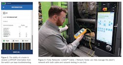
Industrial Ethernet network switches use link layer discovery protocol (LLDP) or Cisco discovery protocol (CDP) that allow them to discover connected devices and advertise their capabilities. Testers with the ability to receive LLDP or CDP from a switch are ideal for identifying problems at the active equipment by displaying the switch name and advertised speeds (see Figure 2), as well as which switch port and VLAN is assigned to the link. This capability can reduce troubleshooting time on the plant floor where industrial Ethernet switches are typically mounted within control cabinets and difficult to access.
Choosing the right tester is key
Managing a plant network via multiple testers—a qualification tester, a wiremap tester, a tone generator, and a network tester—is not only cumbersome; it’s expensive. Choosing a low-cost cable+network tester that can do it all and one that is specifically designed to support industrial Ethernet networks can eliminate the cost of an outside contractor and save time (see Figure 3), letting you effectively bring new plant machinery online and quickly resolve any network failures to avoid costly downtime.
This story originally appeared in the July 2021 issue of Plant Services. Subscribe to Plant Services here.
Mark Mullins is one of the founding members of Fluke Networks, starting in 1993. He has been involved in all of the key areas of the business, including cable testing, network troubleshooting and analysis. He currently oversees the company’s Global Communications efforts, keeping customers and prospects up-to date on cable testing products and technologies. As a member of the Ethernet Alliance Marketing Committee, he is responsible for promoting the Gen 2 Power over Ethernet Certification program. He holds a BS in computer science and an MBA from the University of Washington.


