Become a compressed air sleuth and identify alternative approaches to resolve compressor problems
It’s critical to look properly at all potential causes for a compressor problem in a plant. It’s amazing how much we don’t know about what we don’t know. It’s interesting how much operators don’t know about compressors they’ve operated for many years. It’s also amazing how much compressor engineers don’t know about the operation of the rest of the plant where they’ve worked for years. Therefore, it’s critical to get input from other engineers and technicians who notice the problem, who are affected by it, and who are actually related to it.
It’s often useful to collect input from other engineers one at a time. Otherwise, for example, in a formal meeting, engineers or operators tend to be inhibited about offering their impressions of the real causes of problems.
It’s generally a good practice to identify alternatives for approaches to resolve a compressor problem. In other words, brainstorm for solutions to a problem. Brainstorming is collecting as many ideas as possible. And the next step is screening them to find the best idea. Other important aspects of the compressor problem-solving process is continual observation and feedback.
Case study 1
This case study is about the inter-section temperature measurement for a centrifugal compressor with a sidestream to measure temperature inside the compressor before and after the sidestream. The operator team claimed that inter-section temperature measurements weren’t provided and they were unable to determine the actual compressor performance and monitor the compressor operation. They also highlighted they were unable to detect emerging problems or properly adjust the anti-surge system because of the lack of the inter-section temperature measurement. This is a request that a machinery engineer may face for any compressor with a sidestream.
A quick assessment of any conventional-type centrifugal compressor with a sidestream can show that installing temperature measurement sensors inside the compressor is a very risky task that requires lots of effort. It’s an extremely difficult task to provide direct temperature sensing for the process gas inside a compressor in predefined locations of a complex mixing section. The compressor can be seriously damaged or even destroyed in the modification process at site.
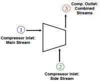
Figure 1. This schematic shows a conventional-type centrifugal compressor with a sidestream.
Investigations showed that temperatures inside the compressor, before and after sidestream mixing, aren’t necessary to estimate power and performance of a centrifugal compressor with a sidestream. The following equation can be used to calculate the power and efficiency of a centrifugal compressor with a sidestream (Figure 1).
PCOM = m3 h3 - m1 h1 - m2 h2 (Equation 1)
= (m1+m2) h3 - m1 h1 - m2 h2
Where:
PCOM represents compressor power (with a sidestream)
m represents mass flow
h represents enthalpy
The isentropic efficiency could be calculated by comparing the ideal power and the actual power.
To better explain the presented method, the compressor performance can be viewed as an overall performance — a compressor overall efficiency — which includes the stages (impellers) from the inlet to the sidestream (Section 1), the sidestream mixing section, and the stages (impellers) from the sidestream to the outlet (Section 2). For a compressor with a sidestream, there are some losses at the sidestream mixing section. The overall efficiency of a centrifugal compressor with a sidestream is lower than one for a comparable centrifugal compressor without a sidestream.
Based on experiences, unfortunately, some compressor manufacturers calculate the efficiency of compressors with sidestreams, neglecting the sidestream mixing section losses. They just simulate impellers and sections without any losses in sidestream mixing sections. Alternatively some other vendors may consider these losses but with inaccurate methods, which result in losses lower than actual ones. This also helps vendors to claim better efficiency and performance, which may be good for their sale and advertising. The compressors with sidestreams are usually used in special processes such as ammonia, syngas, or propane, where the ASME PTC-10 type-1 performance test cannot be implemented in the vendor shop. The ASME PTC-10 type-2 test has many shortfalls for compressors with sidestreams, and this test can’t identify the above-mentioned efficiency gap. The unrealistic efficiencies claimed by vendors never tested before the commissioning of the plant. This efficiency gap between the actual performance and the vendor-claimed efficiency, due to sidestream mixing section losses, has been identified for many compressors. A machinery engineer should always expect this efficiency gap for any compressor with sidestreams.
The compressor theoretical efficiency depends on many details such as the impeller specific-speed and impeller design, as well as details of sections, but this is usually limited to approximately 70–79% for a compressor with traditional 2D impellers. Many compressors with sidestreams, using conventional 2D impellers, have claimed efficiencies in the range of 72-77%. However, the actual efficiency for these machines could be 65-71%, and for some machines even below 65%. The reason is the losses in mixing sections. These losses are relatively high if mixing sections were not designed properly or in cases that there are operational deviations. When operating process conditions in inlet or sidestream don’t fully match with design conditions, much higher losses, compared to losses at design conditions, can be expected. For example, pressure deviations at a sidestream — sidestream pressure lower or higher than the rated pressure — can result in great losses and operational problems.
Another issue is that the operation team needed the temperature after the sidestream to properly operate and adjust the anti-surge system. The fact is the gas temperature after the sidestream can be properly estimated using compressor formulations — no need for the direct measurement. The following equations can be used for the mixing section:
PA=PB=PC (Equation 2)
mC=mA+mB (Equation 3)
hC= (mA hA + mB hB)/mC (Equation 4)
Where:
A represents the discharge of Section 1
B represents the sidestream
C represents the mixed suction to Section 2
m represents mass flow
P represents pressure
T represents temperature
h represents enthalpy
TC can be found by working back through the gas property — for example, Mollier diagram — knowing hC and PC:
hC= (mA hA + mB hB)/mC (Equation 5)
TC may also be approximated by the following rough formulation:
TC= (mA TA + mB TB)/mC (Equation 6)
Section 1: from suction to sidestream.
Section 2: from sidestream to discharge.
Integrally geared compressor
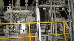
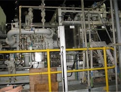
An integrally geared compressor for a critical service in a plant could not achieve 99% availability defined by the risk assessment team for the commercial viability of the plant (Figure 2). The team asked what should be done to this machine to achieve availability greater than 99%. Investigations showed a backup, or standby, compressor for this machine is necessary, if 99% availability should be achieved. There are many options — for example, an oil-flooded screw compressor, another similar integrally geared compressor, or a conventional-type centrifugal compressor. After a study of all options, the best recommendation was to buy a backup, or standby, compressor that uses the similar compressor model with an improved packaging concept. The new compressor will be a standby, or backup, machine. This should be similar to the existing compressor model to reduce spare parts and operational and maintenance complexity. This selection can also provide a reasonable cost because an integrally geared compressor is cheaper than a comparable conventional-type centrifugal compressor.
Figure 2. This integrally geared compressor is a well-designed package that can achieve a high availability.
The following improvements were recommended for the compressor package:
- Two identical E-motor driven lubrication oil pumps should be used instead of a single pump in the existing compressor package (electric power supplied from different electrical sources).
- The existing compressor used an inlet throttle valve (ITV) for the capacity control. A better capacity control method, inlet guide vane (IGV) system, should be used.
- Combined anti-surge/control system is recommended. The proposed control option is a combined control system, rather than two independent control loops, used in the existing package. This control solution should use the anti-surge valve (bypass) only for the anti-surge application. This can eliminate the root cause of some control issues. Trip and alarm parameters and limits should also be improved for a better operation.
- An optimum and improved system of condition monitoring for the package, including compressor and electric motor, should be considered. Online vibration monitoring should be provided for the electric motor.
This new compressor skid can also be used as an example to improve the existing skid.
Another proposal was to purchase a spare bare compressor (compressor frame) and keep it in the warehouse for a quick compressor replacement in case of any issue. This proposal was rejected.
More than 65% of all compressor package issues and problems are related to auxiliaries and accessories, rather than the compressor frame itself.
A spare machine, not a spare part, should always be installed and operational. It is a mistake to buy a machine, such as a pump or a bare compressor, and keep it in the warehouse. There were cases in which a spare machine in the warehouse couldn’t be matched inside its package. In most cases, machines were damaged or destroyed in the warehouse. Machines are complex and delicate systems and require constant attention and monitoring to make sure they will work when needed.
Case study 2
The operations team reported a poor temperature control of a lubrication oil system in a critical compressor package. They asked for a new three-way temperature control valve with internal thermostat to replace the existing two-way valve and modify the existing lubrication oil system. The lubrication oil system of this machine has a two-way temperature control valve (TCV) supplied by a reputable valve vendor in a cooler bypass line. There is a separate temperature sensor at downstream and a dedicated control loop. This TCV and temperature control arrangement is acceptable as per API-614. Changing this valve to a three-way temperature control valve cannot be a good idea. The three-way temperature control valves with internal thermostat had been used in lubrication oil systems of many rotating machines. The operations team had experiences with those machines and assumed that those lubrication systems didn’t have temperature control problems because they used three-way valves with a special trade name. However, the performance and reliability of these three-way temperature-control valves with internal thermostat are actually not better than the two-way temperature control valves in the cooler bypass line, such as one installed in this oil system. It should be noted that, as per API-614, the oil bypass valve should be a flanged and pneumatically operated (air-to-open fail-close), and both a two-port or three-port temperature control valve are acceptable. In fact a two-way temperature-control valve installed in the cooler bypass line is the recommended design in API-614, and theoretically this could be considered a better solution compared to some three-way temperature-control valves with internal thermostat. The three-way temperature control valve with an internal thermostat is also acceptable, but as an alternative option.
The operation of the TCV and control system was investigated. The operational investigations showed the two-way valve needed maintenance and some adjustments after many years of operation. The valve performance was acceptable after this brief adjustment.


