Improve compressor efficiency at the Dirty 30
In brief:
- Air leaks are most likely to appear in the line connecting the distribution header to the tool using the compressed air.
- Air lines should be sized for low pressure drop at peak flow rates, not at average flow rates.
- Select full-port disconnects, FRLs, and line fittings to minimize pressure drops.
In recent years, manufacturing plants have recognized the importance of improving compressed air system efficiencies. Two key points for plant engineers and energy conservation champions to focus on are to eliminate leaks and to reduce air compressor operating pressure to the lowest set-point possible.
Leaks and pressure drops can occur anywhere, both on the supply side and demand side. These two wasteful energy consumers are typically most prevalent within the final 30 ft between the main distribution headers and the operating equipment, commonly referred to as the “Dirty 30.” This includes pipe runs and associated items such as valves, pressure regulators, filters, lubricators, quick disconnects, hoses, and flexible connections.
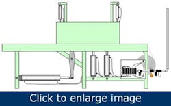
One common practice resulting in excessive pressure drop is the use of inadequate pipe size between the main distribution header and the production equipment. The pipe is undersized frequently because the installer or designer based the selection on the expected average compressed air demand only, but didn’t take into consideration the rate of flow. For example, let’s assume that a packaging machine (Figure 1) specification lists the compressed air requirements at 60 cfm. The pipe from the distribution header to the packaging machine is a 30-ft straight run. If we refer to a Friction Loss Through Pipe Chart, a 1-in. pipe might be considered adequate because it shows less than a 0.5 psi drop.
Figure 1: Pay attention to the sizing of components between the air header and the end uses.
But this assumes the 60 cfm is consumed equally throughout the minute. If, however, the packaging machine requires 1-sec actuations, each consuming 10 cubic ft of air once every 10 sec at a rate of 6-cycles/min, the rate of flow becomes much higher than the average. Although the average flow is 60 cubic ft/min, the instantaneous rate of flow actually is 600 cfm during each 1-sec cycle. (10 cubic ft/sec x 60 sec/mine is 600 cubic ft/min). In this instance, the 1-in. pipe run would have a pressure drop exceeding 30 psi. One way to overcome this could be to set the compressor pressure higher to compensate, causing the entire system to consume more energy.
When operating positive displacement air compressors in the 100 psig range, every 2% decrease in operating pressure requires about 1% less input power. For example, reducing a 100-hp rotary-screw air compressor’s pressure set-point just 5 psi from 100 psig to 95 psig reduces the input power to compress air by 2.5%. At $0.10/kWh, this calculates to approximately $1,900/year in energy cost reduction. Calculated energy cost reduction is based on the compressor running at full capacity, operating 8,760 hours per year with a motor efficiency of 93.6%. In addition, a decrease in system operating pressure reduces compressed air consumption at unregulated end users.
The correct repair would be to increase the size of that connecting pipe. With these effects combined, the use of a 2-in. pipe in the packaging machine might have reduced the air compressor’s power requirements by as much as 20%.
Point-of-use filters, regulators, and lubricators (called FRLs) provide a clean, stable, and lubricated compressed air supply. The Compressed Air Challenge recommends the following when it comes to filters, regulators and lubricators:
- Filter and dry the air only to the level required for each point of use or application.
- Use low pressure drop, long-life filters.
- Size filters, regulators, and lubricators based on the rate of flow.
You must understand the flow characteristics of air system devices, equipment, and tools and consider them in your compressed air supply system design and installation. In many cases, we find FRLs undersized for the maximum flow rate. Under-sizing any of these components, or sizing them solely on pipe-thread size of other connected components, will result in an increased pressure drop.
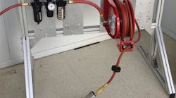
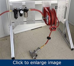
For example: the regulated pressure on an FRL system is set at 80 psig, However, the pressure drops to 50 psig or less when a downstream machine cycles and consumes compressed air (Figure 2). This usually results in the incorrect diagnosis of low air pressure in the mains. Often the compressor discharge pressure is raised to compensate for the FRL pressure differential. The correct repair would be to replace the FRL with properly sized components.
Figure 2. Proper sizing of components between the air header and the tool will pay dividends in lower energy cost.
Timely maintenance, or replacement of point-of-use filter elements, is critical to maintaining or reducing pressure drop. Replace filter elements when the cost of the pressure drop exceeds the cost of the replacement element. Would you replace a $10 filter element or would you increase your compressor discharge pressure 5 psi costing $1,900/year? Maintain acceptable filter element energy efficiency by monitoring the pressure differential across the element. Replace the element on a scheduled basis, or when the differential exceeds the typical loaded pressure drop the manufacturer specified. If properly sized and correctly installed, the typical point-of-use filter, regulator, and lubricator provide tools and equipment with a clean, stable, well-lubricated air supply. When not maintained properly they can cause tools and equipment to run improperly or wear prematurely.
[pullquote]Another major source of pressure drop typically found in the Dirty 30 is inadequately sized hoses and quick disconnects. Quick disconnects are used to transition from hard piping to hose, and at the final connection to the operating equipment or tool. Usually, quick disconnects are selected based on the size of the supply line pipe-threads. However, many quick disconnects aren’t full-port-designed. Often the female half of a quick disconnect coupling uses a spring-loaded ball-against-seat design to prevent compressed air escaping to atmosphere when disengaged. Even when engaged by the male fitting and lifted off its seat, the ball and spring still introduce a pressure drop. The internal orifice size of a ½-in. quick disconnect might be only ¼ in. or less. We have recorded pressure drops of 30 psi and more between the distribution pipe and the final connection to the equipment or tool, especially if a single hose run feeds multiple connectors. Pay attention to sizing quick disconnects properly.
A good alternative to the standard quick disconnect is a version with a full-port design. These disconnects are similar to a full-port ball valve. The internal orifice is the same size as the pipe thread size and doesn’t have a ball and spring to introduce pressure drop.
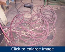
In addition to the pressure drop the quick disconnects cause, the pressure loss through the hose feeding the equipment or tool should be considered carefully. Figure 3 illustrates an extreme example of a poor installation. Too often we see equipment or tools connected with ¼-in. hose when the application requires a 3/8-in. or ½-in. hose. For example, Compressed Air Challenge’s Best Practices for Compressed Air Systems manual shows that a 20-cfm air load at 95 psig delivered through 8 ft of ¼-in. air hose has a pressure drop of 9 psi. In addition, as noted in the earlier packaging machine example, the hose also has to be designed to accommodate the connected equipment’s maximum rate of flow rather than the average. In many instances, when the maximum rate of flow is considered, a diameter twice or three times that of the originally selected hose may be required. Additional problems can be introduced when an excessive length of hose is installed because it either was a bargain or it came as part of a hose reel. In some applications, we’ve seen as much as 100 ft of hose when the application required only 10 ft. Hose assemblies should be designed and installed with low pressure drop hose barbs and disconnects, and should be only the length required to do the job.
Figure 3: Extremely poor installations definitely demand greater compressor discharge pressure if they are to function properly.
Reducing pressure drops in the Dirty 30 allows a system to operate more efficiently at lower pressures. In addition to the energy savings resulting from operating the compressors at a lower pressure, any unregulated leaks will waste less air, thereby reducing energy requirements and associated costs.
It’s not uncommon to find a plant’s total compressed air leak rate at 20% to 30% of the total demand, maybe even higher. With an energy rate of $0.10/kWh, a 100 cfm-leak costs approximately $17,500/year. This assumes a compressor efficiency of approximately 4 cfm/hp; operating 8,760 hours/year and a motor efficiency of 93.6%. Compressed air production is expensive; leaks not only contribute to higher energy costs, but also cause other operating losses. Air system pressure drops, as a result of higher flow rates due to leaks, might force you to operate the compressors at higher pressures, which further increase energy costs. This leads to heavier loads on the supply side equipment and results in greater wear and increased maintenance and repair costs.
Leaks can occur anywhere in the compressed air system. However, because of the numerous components and fittings typically used to connect the operating equipment to the air header, the Dirty 30 is a prime candidate for leaks.
| Paul Shaw is general manager at Scales Industrial Technologies in Milldale, Connecticut. Contact him at [email protected] and (800) 627-9578, ext. 3118. Niff Ambrosino is chief operating officer at Scales Industrial Technologies. Contact him at [email protected] and (973) 890-1010 ext. 5230. |
When instituting a leak repair program, we recommend starting by identifying and repairing the obvious leaks. These typically are larger leaks that can be heard or felt while production is running. If possible, with production down, pressurize the Dirty 30 to detect smaller or more secluded leaks. An ultrasonic acoustic detector is a good tool to aid in leak detection.
Remember that identifying and repairing compressed air leaks doesn’t always translate directly to a corresponding reduction in compressed air energy cost. Typically, as recommended in the Compressed Air Challenge’s seven-step action plan taught in the Fundamentals seminars, compressor controls need to be adjusted or modified to capture a reduction in energy costs directly proportional to the reduction in compressed air demand.
Compressed air often is the most expensive utility used in a manufacturing plant. However, paying close attention to the Dirty 30 as part of an overall compressed air energy savings program can reduce energy costs, thus increasing your company’s bottom line.


