Experts are quick to point out that the biggest gains to be made in compressed air system energy efficiency are on the demand side. Most plants are running higher system pressures, full of leaks and using compressed air for purposes where less energy-intensive options exist. And Plant Services has published thousands of words about where to find and how to fix those demand-side excesses.
But the fact that the demand side is by far the larger part of the problem hasn’t fazed the engineers who toil daily to increase the efficiency of the compressors themselves. And like good engineers always do, they’ve made quiet but excellent progress during the past 20 years.
From inlet filters to oil separators, airends to controls, compressor and compressed-air equipment manufacturers are driving down the amount of energy it takes to generate a given flow — your kWh per 100 cfm. Here’s how they say they’re doing it, and what you need to know to take advantage of their labors.
Principles start with p
A few percent here, a few percent there — it doesn’t sound like much, but the purchase price of a compressor typically pales in the face of its life cycle cost. “What’s the cost of a compressor?” says Mike Bakalyar, manager, enhanced services, Gardner Denver (www.gardnerdenver.com). “Over its life, a 150-hp machine at $0.10/kWh will cost $1,200,000.”
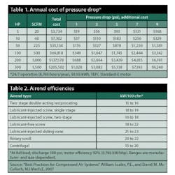
Some of those percentage improvements are obtained by limiting pressures. Minimizing the maximum compression pressure has a direct and well-known relationship with efficiency — the guideline is that every 2 psi reduction increases efficiency 1%. Annual savings from reducing a pressure drop between the airend and the point of use is shown in Table 1.
“It’s all about specific performance,” says Harold Wagner, national sales manager, Kaeser (www.kaeser.com). “You must compare the total amount of energy put into a compressor to produce the compressed air at the specified pressure at the compressor discharge. That includes everything from cooling fans to drive motors and transmission losses.”
Begin at the end
Specific performance starts with the right airend — the compressor itself — for the job. Highly developed over many years, each commonly-available industrial airend technology has settled into a range of efficiency, shown in Table 1 for units under typical conditions at full load. Size, manufacturer, efficiency of the driver (typically a motor with or without a variable-speed drive) and the operating conditions (pressure, turndown, etc.) affect this basic efficiency range.
There are reasons other than efficiency to choose one technology over another, but Table 2 is an interesting place to calibrate your expectations. The advances we discuss apply to compressors based on many types of airends, but screw compressors have become the most common type for industrial applications, so the examples tend to reference screw impellers. As Table 2 shows, multiple stages can offer a significant efficiency advantage at common industrial system pressures.
Another fundamental is the drive system. “Direct drive is most efficient,” says Hannu Heinonen, global rotary line manager, Fu Sheng Industrial Co. Ltd. (www.fusheng.com). “Belts can handle lower horsepower, but start at 1% loss and can slip to 6%. Gears require less maintenance and last longer, but add 2% to 4% loss.”
Table 2 also shows a difference between lubricant-injected and lubricant-free screws, due to the sealing effect of injecting oil or water into the screws. But what goes in must come out. “Oil-flooded screw compressors are more efficient than oil-free, but oil must be separated,” says Steve Centers, manager, electrical engineering, Quincy Compressor (www.quincycompressor.com). “New separation element materials take the oil content down to 1 ppm instead of 3 ppm to4 ppm, but separators can build up back pressure.”
The choice of lubricant for oil-injected compressors can materially affect energy efficiency by reducing friction and dimensional changes caused by varnishing. “Using water as a lubricant offers about the same efficiency as oil lubrication, about 15% better than dry,” says Heinonen, “Water-injected units also offer almost adiabatic compression because of good cooling, but must be run at higher speed due to the lower viscosity. There’s no oil to change, but service life is shorter than typical oil-lubricated compressors. You have to plan for 24,000- to 30,000-hour rebuild intervals.”
That good-guts feeling
Manufacturers are making incremental gains in airend efficiencies by matching sizes and designs more closely to requirements, by using simulation software to refine designs, and by producing components with higher accuracy and precision. “You need the right size rotors with the right profile,” says Harish Shah, associate fellow, Sullair (www.sullair.com). “Do you make specific machines or go mid-path to cover ranges of speed, horsepower and capacity?” Manufacturers with more choices of housings and rotors are more likely to offer the highest efficiency at a given pressure and flow.
“Several years ago, we began an initiative not only to optimize the design of our airend, but to specifically match the airend size to the horsepower range,” says Wagner. “We have more than 30 airends to select from when determining which one is going to be the most efficient.”
Of his company’s most recent line of 75-plus horsepower machines, “It’s not just different rotors — it took us six new airends to cover the range,” says Bryan Fasano, marketing manager, rotary screw compressors, Gardner Denver.
Sizing and design are more critical for direct-drive applications, where speed choices are limited by available motors. “Direct drive has to be optimized in the motor speed or by altering the airend,” says Heinonen. “Most compressors in the U.S. are optimized for 125 psi; it’s 110-115 psi elsewhere. And most equipment needs only 75-80 psi.”
There’s more at stake than efficiency. “When matching the airend to the horsepower, more options are better, to avoid overkill and marginality,” says Bill Kennedy, rotary screw product manager, FS-Curtis (www.curtistoledo.com). “A marginal system raised from 125 psi to 150 psi or 175 psi will require a higher-performance-factor motor.”
As they approach more closely the optimum size and RPM for each application, engineers are gaining incremental improvements by improving rotor profiles and housing designs using computational fluid dynamics.
“A lot of work has been done using computer simulation on the inlet valves, etc. to reduce pressure drops throughout the machine,” says Fasano. “It’s ideal to have a first-stage compressor with a rotor wrap optimized for the interstage pressure — 40 psi to 60 psi — then take that up to 100 psi or 125 psi or even 150 psi.”
On the design of screw impellers, Centers says, “We’re continually working on improving profiles. The geometry is pretty complex, and also the machining.”
Impellers traditionally were made in uniquely timed, matched sets. Moving from machining to hobbing and grinding has allowed tighter tolerances that increase efficiency while allowing drop-in replacement of individual parts. “Improvements in manufacturing have lead to tighter tolerances and better volumetric efficiencies,” says Kennedy. “For example, we no linger need a seal strip at the end of a rotor.”
Several experts commented on the trend to smaller airends. North American designs have typically been larger and have operated at lower rpm than European models, but that’s no longer the case. Smaller, higher-speed airends can hold tighter tolerance, making them at least as efficient and durable as larger models with lower initial cost.
Engineers have worked on package design, eliminating pressure drops through tubing, fittings, coolers, etc. A differential of 3.5 in. WC across an intake air filter equals a 1% loss in capacity. “Optimizing all this can pick up 5% to 8% versus 10 years ago,” says Shah. “New filter designs start with a lower pressure drop that increases half as fast over time. They cost a little more but they pay it back in three days.”
When comparing airends, don’t rely solely on the manufacturers’ spec sheets. See if the performance data has been verified by the Compressed Air and Gas Institute (CAGI, www.cagi.org). “The CAGI Third-Party Performance Verification Program is an important tool for evaluating and verifying specific package performance,” says Wayne Perry, technical director, Kaeser.
Improvements at partial loads
While the mechanical engineers have been extracting higher efficiencies from airends, the electrical contingent has been working on motors and variable-speed drives (VSDs). “The 1990s brought the Motor Challenge,” Shah says. “A premium-efficiency motor offers a 1% to 3% improvement.
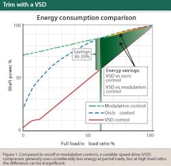
“Then came the variable-speed drive, which is now on one of every four machines sold,” says Shah. Screw compressors are efficient at full load and unload. “Part-load efficiency can be all over the map,” he says. In the 1970s, partial loads were handled by throttle suction modulating, in the 1980s came variable displacement, where the unneeded portion of the compressed air is returned to the suction side. On/off, modulation and VSD power consumptions are compared in
Figure 1.
“The shape of the on/off-controlled power consumption curve depends on the air storage capacity,” says Heinonen. With smaller volume, the power consumption curve approaches the modulation control curve. In very large volume systems (relative to compressor capacity), it approaches the VSD curve. “The savings of VSD controlled compressors are illustrated at 60% of full load as this is often thought to be the average screw compressor load in air systems,” he says.
Along with often improving efficiency at part-load, VSD adds a soft start that reduces peak electrical loads compared to wye-delta or across-the-line motor starters. It can reduce pressure swings to 1 psi to 2 psi, from up to 10 psi, which reduces wasteful peak pressures and improves consistency of quality in the plant. “The motor lasts longer — there’s no limit to the number of starts — and it has a high power factor so you don’t need to add capacitors to correct it,” Shah says. “The costs are coming down — a drive that cost $18,000 in 1975 now can be had for $2,000, and there are rebates and tax incentives. You can add one to an existing machine.”
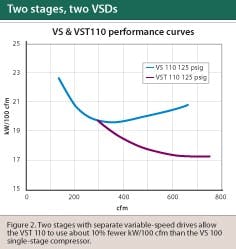
A two-stage compressor can benefit from using a separate VSD for each stage (Figure 2). “While our single-stage VS series compressors are efficient, even greater efficiency is achieved with two stages,” says Tom Beck, rotary screw marketing, Gardner Denver.
“Using two motors with VSDs, each driving its own airend, we can control the inter-stage pressure,” says Fasano. “The resulting two-stage variable-speed compressor is about 10% more efficient than a single-stage variable-speed unit.”
VSDs can save a lot of energy in the right application as trim compressors, but they are not a panacea, warns Niff Ambrosino, general manager, Scales Industrial Technologies, Inc. (www.scalesindtech.com). They might be chosen for the wrong reasons, in which case they can’t deliver the expected ROI. Ambrosino says, “Very often, choices are driven by rebates, which are prescriptive — ‘install a variable-speed drive’ — rather than based on pre- and post-measurements of consumption.”
Today’s frontier: Controls
“Many factories are so lean they’ve got one person performing maintenance,” says Centers. “Our equipment must be able to give them a heads up so they can schedule service and prevent problems.” Quincy’s QSI compressors use a Siemens HMI with a built-in Web interface that can publish trending and operational data automatically.
If an air filter is clogged or a pressure gets too high, for example, the PLC will alert maintenance via e-mail delivered to a laptop or cell phone. “E-mailed status reports cover more than 20 parameters with date-stamped readings on compressor conditions ranging from hours of operation to air and fluid temperatures,” Centers says.
But many facilities have an eclectic mix of old and new compressors, of various sizes with different controls. On both old and new systems, energy-management control can stabilize system pressures and optimize the combination of compressors to run at a given load. “The biggest efficiency gains over the next few years will be in the area of controls,” says Perry. “Properly controlling multiple compressors holds the most potential for energy reduction.”
“The ‘$mart Sequencer’ control system measures power consumption and flow,” says Ambrosino. “For example, a new system might measure 5.8 cfm/kW. If the controls go out of tune or there’s system deterioration, it might drop to 5.2, and you know there’s a problem.”
For the past five to 10 years, efficiency increases have come from the ways that compressors are controlled at less than full load, but they’re still typically less efficient than at full load. “If the floor is using 100%, it might be 4.8-4.9 cfm/kW. At lower demand, it might drop to 3.1 or even 2.4,” says Ambrosino. “The sequencer does its job and minimizes the drop. It combines and controls multiple compressors to maximize efficiency. If something goes wrong, it alarms, and it can help you see if the problem is on the supply or demand side.”
Fixed-speed compressors should be run at full capacity, with partial loads handled by a variable-speed unit. “Most multiple compressor systems aren’t optimized. You find a ton of different things, but many plants are running too many machines not at their optimal point,” Bakalyar says. “The objective is to make sure you have only one asset in trim at any time, and the rest at full load. Too many people run too much horsepower because they don’t have a way to turn a compressor back on when needed.”
Energy also can be saved by reducing excess pressures that used to be needed to sequence the compressors. Traditional staggered switch settings require a 3 psi to 5 psi offset for each additional machine, which makes it hard to limit total pressure. And there’s no way to optimize the combination of compressors for a specific load condition. “Offsets often add up to 10 psi to12 psi, so reducing that to 3 psi can save 5% of energy costs,” says Kennedy. “In a year of 24/7 operation, the energy savings can be three times their acquisition cost. Do a system audit — the ROI can be very attractive.”
Plants that install instrumentation to monitor flow and power in real time, all the time, can see if they’re on track for efficiency. “On install and tune, we establish kW/100 cfm, and monitor it to detect if the system is slipping,” says Bakalyar.
A dirty oil separator or blinded inlet filter will increase power consumption. With instrumentation, you can tell if results are being sustained. You can go back and check, or you can build tools for flow and power measurement into the system. You can develop a metric that lets you know when to call someone in. You have a report card 24/7 and information for monitoring and for first respondents.
Systems that monitor power and flow also can track a myriad of other variables to enable predictive maintenance. “For a price, you can add anything you want to monitor,” says Paul Blake, manager, gas compressor engineering, Quincy Compressor (www.quincycompressor.com), such as differential pressure across an air filter, dew point, pressure drops or cooling water temperatures.
You also can start anticipating controls that are capable of reducing power on a signal from your local electric utility. These will work with power companies’ demand response programs and make it possible for even small users to participate.
“Everybody is recognizing energy costs keep going up, demand charges keep going up,” says Shah. “Many people find they already have the equipment they need, they just need to operate and maintain it correctly. They need controls to sequence and run compressors at the optimal point.”
E-mail Editor in Chief Paul Studebaker, CMRP, at [email protected].
-----------------------------------------------------------------------------------
Clean and dry
Separators, filters and dryers can reduce efficiency by introducing pressure drops. “Filtration can be reduced to less than 1 psi drop versus 3-4 psi,” says Niff Ambrosino, general manager, Scales Industrial Technologies, Inc. (www.scalesindtech.com). The energy savings is proportional to the ratio of absolute pressures.
The accepted pressure drop through a dryer at nominal capacity is 5 psi. “That allows less-expensive equipment but means a loss of 2.5% in efficiency,” says Bill Kennedy, rotary screw product manager, FS-Curtis (www.curtistoledo.com). “You can size the dryer for 2-psi maximum drop and pick up 1.5% in efficiency. Using inlet filters with deep pleats, lots of area and high void volumes can improve efficiency another 1.5%. At the same time, you’re improving pressure uniformity and air quality, which improves production quality and uniformity.”
Computer-aided simulation was the basis for the turbulence-free design of the Ultra-Filter compressed air filter by Donaldson Company, Inc. (www.donaldson.com). Filtration media, pleating and construction reduce pressure losses by 50% while increasing separation efficiency. A 3-psi lower differential pressure over 8,000 operating hours at 600 scfm saves $1,452 per year (based on 100 psig operating pressure, 120 kW installed power and $0.08/kWh).
The most economic time for filter changeout is determined by continuously measuring the differential pressure. An integrated microprocessor compares the higher energy costs caused by pressure loss with the costs of a new filter element, determines the most cost-effective element replacement time signals the need for filter changeout with LEDs.
Refrigerated driers add their own energy consumption. “Do you really want to dry the air to -40°F? Or will -35°F do it?” asks Bill Scales, P.E., CEO of Scales Industrial Technologies Inc. “That can cost about 0.8 kW/100 cfm, sometimes more like 2 kW/100 cfm to3 kW/100 cfm.”
Traditional refrigerated dryers either run constantly or toggle the refrigerant compressor by storing cold in glycol or sand. “That introduces complexity, pumping losses and temperature swings that cause the dew point to vary,” says Kennedy. “Computer controls and sensors can cycle the refrigerant compressor to handle varying loads with just the thermal mass of the aluminum in the heat exchanger. On a desiccant dryer, they can purge based on demand and control the purge flow to optimize air use.”


