For the first half of the 20th century and through the 1950s and 1960s, the predominant industrial air compressor was the positive displacement double-acting, water-cooled reciprocating design. The predominant control methodology allowed for three to five control load settings: 0% to 50% to 100% or 0% to 25% to 50% to 75% to 100%. These settings responded to the systems dynamic demand and the power consumption was quite close to the load factor, while the unloaded horsepower ran between 18% and 20% of maximum.
The mechanisms that accomplished this essentially changed the geometry of the compression chamber cylinder with a variety of devices that held a set of valves open that allowed air to move in and out of the chamber without compression. With respect to efficiency, this design generally consumed 15 kW to 16 kW per 100 CFM of compressed air. Todays compressors and controls barely reach that level of efficiency.
Then, why have reciprocating designs fallen out of favor relative to the rotary compressor that is so predominant today?
Problems with pistons
A double-acting reciprocating compressor is a large belt-driven cast iron water-cooled compression chamber. This design generates unbalanced forces that require large concrete foundation pads. Installation is arduous.
The components are shipped separately. Think of an Erector set having a compressor, motor, starter, belt drive, aftercooler, receiver, condensate drain traps and dozens of minor pieces. When you finally assembled everything into a working device, youd also require much more floor space than a rotary-screw compressor. Further confounding the picture, the only cooling option was water. Maintaining the valves, crossheads and main bearings required substantial mechanical skills lacking in todays labor pool.
Additionally, compressed air delivery wasnt smooth, but as intermittent as the piston reversals in the cylinder. This caused a slight but real interruption in the compressed air flow. Large receiver tanks were required to tame it into a smooth air flow for the users. And, dont forget the temperature gain of about 300 degrees Fahrenheit across the compression cycle.
The rise of rotaries
The 1960s saw the advent of rotary compressors. From the outset, these packaged machines received a warm market reception, at least in part because they were generally available as factory packaged units, with motor, starter, aftercooler and controls assembled, wired and ready to pipe and plug in. Because there were no unbalanced forces, vibration was minimal and no heavy foundation was required. A rotary compressor could be placed on any structure that could support its weight.
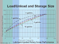
The advertised features and benefits included completely factory assembled, zero unbalanced forces, only about 200 degrees Fahrenheit heat gain, no receiver required because the air flow was smooth, no startup ordeal, no run-in time, and fewer dollars spent on an as-installed basis. The storage myth was soon exposed and the recommended practice today is about three to five gallons of storage capacity per CFM of flow for even the largest machine in the connected fleet (Figure 1).
At the beginning, rotary compressor efficiency was only 18 kW to 19 kW per 100 CFM, or about 18% more expensive to operate than the older reciprocating design. In those days, electricity was considered cheap as most industrial customers paid about $0.025 or $0.030 per kWh, erroneously considered insignificant by the culture of the time. After all, air is free, isnt it?
These figures apply to single-stage lubricant-flooded compressors. Two-stage lubricant-flooded compressors are significantly more efficient and often pay for themselves in a reasonable time. Often enough, the extra investment was justified. The operating efficiency of two-stage units is 16 kW to 17 kW per 100 CFM.
Back in the early days, only load/unload controls were available. The compressor pumped up to a preset pressure, unloaded and ran at idle. Generally speaking, the unloaded horsepower is about 25% of full-load horsepower.
Many operators dont pay adequate attention to the timing of the load and unload cycles on lubricant-flooded rotary screw compressors. The cycle should allow ample time for the sump to blow down, often as long as 60 seconds or more. Each machine is different and blow down times should be measured individually. Short cycling can cause the lubricant to foam and diminish control system life expectancy. It also runs the risk of lubricant foaming out of the compressor inlet onto the floor.
Inlet modulation is inefficient
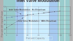
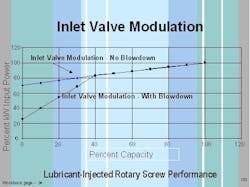
The load/unload approach was supplanted by a variety of modulation controls that features a gradually closing butterfly valve at the compressor inlet. The weakness in this design is miserly little power savings at part load (Figure 2).
Note that:
- at 100% capacity, 100% of the power is required
- at 90% capacity, the power required is 97%
- at 80% capacity, the power required is 95%
- at 70% capacity, the power required is 90%
- at 60% capacity, the power required is 85%
- at 50% capacity, the power required is 83%
- at 40% capacity, the power required is 80%
Also note that at zero capacity, 25% power is required. Most compressor vendors strongly suggest using two guidelines. First, when operating multiple rotary compressors, adjust the controls to run all units at full load and use only one for trim for best energy efficiency, and second, operating several inlet modulation control systems at part load is a terrible waste of energy dollars.
Pushing the frontiers
Soon, technology brought us variable-displacement machines in which the geometry of the compression chamber could change under the influence of a variety of devices. Some machines used a spiral valve, while others used poppet valves that shorten the effective length of the compression chamber. Both approaches allow much better part-load performance (Figure 3). Note that at 100% capacity, 100% of the power is required, but:
- at 90% capacity, 92% power is required
- at 80% capacity, 83% power is required
- at 70% capacity, 78% power is required
- at 60% capacity, 68% power is required
- at 50% capacity, 63% power is required
- at 40% capacity, 60% power is required
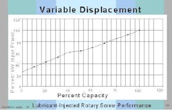
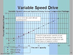
The next big thing in the world of rotary compressors was the introduction of variable-speed drives (Figure 4).
As before, 100% capacity requires 100% power. But:
- 90% capacity requires 91% power
- 80% capacity requires 81% power
- 70% capacity requires 71% power
- 60% capacity requires 61% power
- 50% capacity requires 51% power
- 40% capacity requires 42% power
Control for efficiency
Centrifugal compressors rely on modulation and blow-off, which generally limits turndown capacity to between 70% and 75% of total capacity. When demand falls below that figure, the control frequently goes to blow-off mode and the full capacity is dumped to atmosphere, often piped to the outside. When operating multiple machines, the same suggestions about having only one trim unit and modulating multiple units apply.
A variety of system controls for multiple compressor installations are available. Single master or sequencing controls use one control to sequence or lead/lag the compressors. Multiple master or network controls allow the system to alternate, unload or turn off automatically as system demand changes. Control systems can be integrated with computer-based overall plant energy control systems that monitor HVAC, lights and other items. Pressure flow control devices are separate from compressor controls and are intended to deliver a relatively constant static pressure supply to the air distribution system.
The end of modulation?
It appears likely that the industry will serve the predominant product (rotary screw, both lubricated and dry) with less complicated, more energy-efficient control systems. Youll probably see modulation of every type eliminated, leaving only the choice of load/unload or variable-speed, the two most energy-efficient mechanisms available today. The previous figures lead to that conclusion.
A major caution is in order, though. At full-load conditions, variable-speed units generally will require more power than a load/unload or modulation machine. Thus, in multiple rotary-compressor installations, use only one variable-speed unit. Operate it on trim duty only if you want to accomplish the promised energy savings.
There are other surprises on the horizon. Consider the globalization of the compressor business. Fifty years ago, it was inconceivable that some offshore-based automobile manufacturer would own close to half the U.S. car market. The same is happening in the compressor industry.
The entrepreneurial creativity demonstrated by the young folks coming into the market today is far beyond anything I could imagine. The Electronic Age has everything moving at supersonic speed. The computer I used to prepare this manuscript is almost aging to obsolescence as I use it. We aint seen nothin yet.
Henry Kemp is principal at Strategic Air Concepts in St. Petersburg, Fla. Contact him at [email protected] and (727) 867-4044.
