10 steps to control electrical cabinet problems
In brief:
- Interactions between power and control wiring inside a single electrical cabinet can cause performance anomalies.
- There is a simple 10-step procedure for minimizing those problems.
- One must be aware of the wiring color codes currently in effect before troubleshooting cabinet wiring.
Mixing 480-V three-phase cables and lower voltage 24- or 120-V control wiring and communication cabling in the same cabinet can result in erratic operation or even complete failure of electronic equipment inside the cabinet. Knowing what’s inside the cabinet before you open it, the specific wiring variables to look for once inside, what values to measure, and simple ways to correct problems can help alleviate many erratic and sometimes mysterious control and communication problems.
[pullquote]Electrical cabinets often are designed as a central control point for automation and process control equipment. Inside the cabinet are the programmable logic controllers (PLCs), variable frequency drives (VFDs), and their associated communication and control wiring.
Because the equipment being controlled typically is powered by 480 V, the cabling often must be routed through the same cabinet as the electronic controls — an advantage for both troubleshooting and maintenance. You can observe the indicator lights on a programmable controller, measure voltage on a motor starter, and adjust the drive in the same cabinet.
Safety first
Safety always should be the first concern before opening a cabinet. As a technician or engineer begins work on electronic controls, it’s natural to maintain a narrow focus on the suspect low-voltage equipment and controls and easily forget that working inside a mixed-voltage cabinet exposes workers to dangerous voltages and short-circuit currents. Know the voltages you’ll see before opening that door.
Industrial control panels are required to have durable and legible labels that indicate the rated voltage, number of phases, and the frequency of any supply in the cabinet. Older panels might not be marked. Many panels now have an arc-flash warning label on the panel door. Be aware that an arc-flash label usually provides the maximum voltage in the cabinet and doesn’t mention other supply voltages that might be present. In addition to any label, refer to electrical diagrams and vendor manuals, and even walk down the systems if necessary to help determine voltage supplies present in the cabinet.
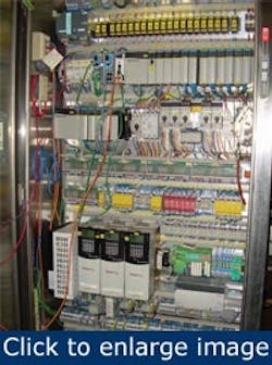
Figure 1. This automation cabinet contains power, control, and communication wiring. A 480-V disconnect handle is at the upper right of the cabinet. PLCs near the top of the cabinet use 24-V inputs and outputs to control a conveyor system while 480-V VFDs near the cabinet bottom drive the conveyor motors.
It’s generally best to stand to the side of the cabinet, if possible, to operate disconnects, release latches, and open doors, just in case something goes wrong. Once the cabinet door is open, make a visual inspection for obvious abnormalities and the smell of burnt insulation (Figure 1). Refer to the appropriate wiring and control circuit diagrams to identify components and terminal strips.
Electromagnetic interference
Notice how wiring enters the cabinet. The 480-volt power conductors and low-voltage control wiring generally will be brought in through separate conduits.
Running such conductors in separate conduits in the field helps to minimize the possibility of electromagnetic interference (EMI). If power conductors are too close to the control wiring and electronic components, you can expect erratic equipment operation.
To reduce EMI, power conductors should be as far away from control and communication wiring as possible. There’s no standard distance definition for what constitutes “close proximity.” Use reasonable judgment. Keep power and control conductors in separate wiring trays inside the cabinet. If for some reason it’s necessary for power conductors and control wires to cross, ensure that they cross at a right angle to reduce the effects of EMI.
Separation of power and control circuitry
Ensure adequate separation of power and control circuitry. To help differentiate between them, notice the conductor sizes and color-coding schemes in use. Control circuit wiring typically is 16 AWG or 18 AWG. Power conductors generally will be no smaller than 12 AWG and often are considerably larger. Grounded conductors are white, are gray, or have three continuous white stripes on any color insulation except green, blue, or orange. Control circuit wires that are white with a blue stripe are the grounded conductor for a dc control circuit. Any control wire that is orange or white with an orange stripe is an ungrounded conductor that remains energized after the main supply disconnect is switched to off. Additionally, red insulation indicates an ungrounded conductor in an ac control circuit and blue insulation indicates the ungrounded conductor in dc control circuits. Conductors that enter the cabinet as part of a multi-conductor cable can have different color schemes. Refer to wiring diagrams as needed.
{pb}Current flowing through a conductor produces a magnetic field in a circular path around the conductor. As the alternating current (ac) flow reverses direction, the original magnetic field collapses and a magnetic field builds in the opposite direction. This process occurs 60 times/sec. If another conductor is within the range of this changing magnetic field, the three requirements for electromagnetic induction will have been met.
- Current flow in the power conductor produces an electromagnetic field.
- A low-voltage control conductor is within the magnetic field.
- There is relative motion between the conductor and the magnetic field as the magnetic field builds, collapses, and reverses direction.
As a result, voltage is induced into the control wiring, hence the term electromagnetic induction. The abnormal voltage and current flow in the control wiring is referred to as electromagnetic interference (EMI), which can produce enough voltage for a PLC or VFD to see a false signal. Or the voltage on the control wiring can be distorted by the EMI and electronic equipment supplied by the control wiring won’t operate properly.
The ungrounded three-phase power conductors in the cabinet have no color-coding restrictions. Typically, brown, orange, and yellow are used for 480-V phases A, B, and C, respectively. Black, red, and blue are used for 208-V or 240-volt phases A, B, and C, respectively. Use caution when identifying and separating wires. Know which color-coding schemes are used inside the cabinet. If in doubt, use a digital multimeter to verify voltage levels at various terminals.
Low voltage instrumentation wiring
Usually, either a twisted pair of conductors or a shielded cable helps minimize the effects of EMI in low-voltage instrumentation wiring. In a twisted pair, one conductor twists around another with the number of twists per inch specified. A shielded cable is a twisted-pair cable with a braid or foil covering running the entire length of the conductors. It also has a thermoplastic jacket for physical protection.
Twisted pair wires help minimize the effects of induction and should remain twisted except at their termination points. The braid or foil covering on a twisted pair helps prevent voltages from being induced into the control wire. This braid or foil must be connected to ground at only one end. A drain wire runs the length of the shielded cable just beneath the foil to put it in contact for the entire cable length. The drain wire, if present, is terminated to ground. The drain wire “drains off” to ground any stray voltages induced into the cable.
If a control circuit is grounded at more than one point, control problems are almost sure to occur. For example, if the drain wire is connected to earth at each end of the cable, or if the cable jacket is accidentally scraped off at some point and the foil contacts grounded metal, a ground loop results. Any difference in potential between the separated grounds will cause unwanted current to flow through the drain wire and foil (the ground loop). When inspecting cabinets, make sure that any insulation placed over the ungrounded end of shielded cables is in place and that the drain wire or any foil isn’t accidentally contacting metal in the cabinet.
- Determine voltages inside cabinet before opening the door.
- Follow electrical safe work practices, including use of PPE and establishing approach boundaries.
- Stand to side, if possible, when opening cabinet doors.
- Inspect wiring and components visually for obvious abnormalities.
- Observe color-coding schemes and differentiate between control and power conductors.
- Verify adequate separation of power and control conductors.
- Verify that power and control wiring cross at right angles.
- Measure voltages to electronic equipment power supplies and verify they’re within OEM ratings.
- Measure voltage at field input and output devices and verify they’re within specification.
- Check integrity of control terminations and tighten terminal screws.
Voltage measurements
Once you correct any abnormalities found during the visual inspection, take voltage measurements to ensure there’s no EMI from power conductors. Use a properly rated digital multimeter to measure and record voltage levels. Input voltage to electronic equipment such as PLCs and VFDs is generally specified as plus or minus 10% of the rated voltage.
Measure voltage to each input and output field device. Be especially wary if any significant voltage is present where it should be absent. This might be an indication of induction from power conductors causing low control circuit voltages. Quite often the source of this problem is in the field routing of conductors and can require considerable troubleshooting to locate the problem’s source. Because the voltage induced into the control circuit wiring varies with power conductor current. It might be necessary to use a recording digital multimeter to identify these variances.
Control wiring terminations
Check control wiring terminations for tightness. Any effects of electromagnetic induction the controls might normally have been able to handle will be exacerbated at a loose termination point, and electronic inputs are affected. Occasionally, wires come loose from pressure connectors, usually because of improper installation. Check each individual wire at its termination point to ensure it’s secure in its connector or under its terminal screw. Tighten each terminal screw.
Proper inspection and maintenance of power and control wiring minimizes electronically controlled equipment performance problems. Loose control wiring and terminal screws, improper grounding techniques, and routing of power and electronic conductors too close together are among the most common, yet hard to find, causes of improper equipment operation. Knowing what’s in your cabinets, making proper inspections, and interpreting control voltage readings will help many of those mysterious equipment problems disappear.
Randy Barnett is an energy auditor at Step1 Energy Audit. Contact him at [email protected].

