There are effective tactics for reducing risk, but most attack the problem in a piecemeal fashion: a fuse here, a relay there, at equipment all over the building. Many electrical professionals are seeing the limitations of traditional protections, and they’re considering a systemic approach that prevents phase-to-ground arc flash from forming anywhere in the system.
Resistance grounding systems are getting a fresh look; their use is increasing 23% a year. If a phase faults to ground, the resistance limits current to just a few amps, not enough to cause downtime by tripping the overcurrent protection device, and not enough to produce an arc flash.
Electrical professionals must consider many things when converting the facility’s solidly grounded system or ungrounded system to a resistance-grounded system. That’s why it’s important to know about resistance grounding, how to implement it, where it can be used and where it isn’t appropriate.
Ungrounded systems
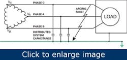
Figure 1. Ungrounded systems can continue to operate if one phase faults to ground but can be subject to transient overvoltages and difficulty locating ground faults.
Some older plants use ungrounded electrical systems, with a delta-connected transformer (Figure 1). Their advantage is they can continue to operate if one phase faults to ground, which is particularly important if continuity of power is critical. For example, chemical plants or refineries involving processes that can’t be interrupted without extensive dollar or product loss might have ungrounded systems. However, ungrounded systems have major problems, including transient overvoltages — a series of arcing ground faults can increase overall system voltage relative to ground to several times its normal value — and difficulty locating ground faults. For these reasons, many have been replaced by grounded systems.
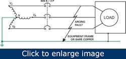
Solidly grounded systems A grounded system (Figure 2) is wye-connected, with the neutral — the center of the wye — solidly connected to ground. Three-phase loads are connected to three phases and single-phase loads are connected either to phase-to-neutral or phase-to-phase. It’s straightforward, and everyone understands how it works. But it also has some drawbacks.
Figure 2. A grounded system is wye-connected, with the neutral solidly connected to ground. While it is simple, ground faults can shut it down and allows severe arc-flash hazards.
The main drawback has to do with ground faults. If a phase conductor shorts solidly to ground, the overcurrent protective device will operate and shut off the affected phase. The other phases might not shut down immediately as well, which can mean that some motor loads might single-phase for a while. In either case, the loads connected to the affected phase get shut down, and production is disrupted.
But the ground fault might not be a solid short to ground; it might be an arc, and not draw enough current to trip the overcurrent protective device. In addition, the arc can initiate a dangerous arc flash, which is why power panels are required to have warning labels, and anyone working on an energized power panel must wear personal protective equipment (PPE).
The severity of an arc flash depends on system voltage and, more importantly, the available current, which can reach 100,000 A. Current-limiting fuses allow only a certain amount of energy to pass before they open the circuit, but they respond best to a solid short circuit, a so-called bolted fault.
There has to be a better way
Another way to ground a plant power system allows it to continue operating even if one phase faults to ground, while getting around the drawbacks of the ungrounded system. Overcurrent protective devices won’t trip, loads continue to operate and maintenance personnel can schedule an outage when it’s convenient rather than having to rush repairs because production has stopped. This grounding method also helps to eliminate of the danger of arc flash, and it protects against transient overvoltages. We’re talking about a high-resistance grounding (HRG) system, also known as a resistance grounded (RG) system, high-impedance grounded neutral system, or a neutral grounding resistor (NGR) system. HRG systems aren’t new; in fact they’ve been mandatory for power wiring in mines for years, and they’re widely used in the petrochemical industry, but only now are they being considered for general industrial use. HRG systems are most often used on systems at or below 600 Vac, which the National Electrical Code (NEC), NFPA 70, article 250.36 permits.
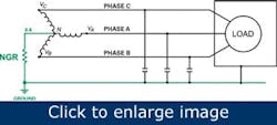
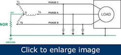
Figure 3. In a high resistance grounding system the neutral point of the wye transformer is connected to ground through a high-value neutral grounding resistor, which normally carries little or no current.
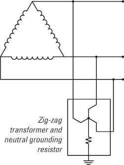
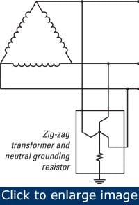
Figure 4. In a delta-connected system a zig-zag transformer is used to create an artificial neutral, which is then connected to ground through the neutral grounding resistor.
How an HRG system works
In an HRG system, the neutral point of the wye transformer connects to ground through a high-value neutral grounding resistor (Figure 3), which normally carries little or no current. An ungrouded system with a delta-connected transformer uses a zig-zag transformer to produce an artificial neutral, which is then connected to ground through the NGR (Figure 4). This transformer carries very little current, so it need not be large or expensive.
During normal operation, the neutral point stays at nearly zero volts; any residual voltage is the result of small differences among the distributed capacitances of the three-phase feeders (Figure 5). The NGR will also limit transient overvoltages to safe values.
During a phase-to-ground fault, the neutral point assumes the phase-to-neutral voltage (277 V on a 480-V system), while the phase-to-ground voltage in the faulted phase will collapse to about zero. The current flowing through the NGR will be the voltage at the neutral point divided by its resistance, which is chosen to keep the current to a few amperes (usually 5 A). This current is too small to trip the system’s overcurrent protective devices and is too small to produce an arc flash. However, it’s important to remember that while resistance grounding prevents arc flash from phase-to-ground shorts, it has no effect on phase-to-phase shorts. Anyone working on an energized panel will still be required to use the appropriate PPE.
Figure 5. During normal operation the neutral point stays at nearly zero volts; any residual voltage is created by small differences among the distributed capacitances of the three phase feeders. The NGR will also limit transient overvoltages to safe values.
Drawbacks and precautions with HRG systems
Some electrical systems have both three-phase and single-phase loads. Facility systems — in office buildings, for example — generally use a system neutral for the 277-V circuits for lighting and HVAC blowers. The NEC doesn’t allow that neutral to be distributed, which makes it necessary to convert from a neutral running throughout the facility to isolation transformers. If single-phase loads must be powered from the system, they must be connected through a 1:1 isolation transformer or converted to line-to-line loads.
In industrial faculties, some three-phase loads — variable-frequency drives, for example — have filters on their input lines. These filters must be rated to withstand the elevated neutral point voltage that occurs during a ground fault. The filters on many or most modern VFDs are rated to handle this voltage, but it’s still a good idea to verify this fact.
If the grounding resistor opens — by accident, by mistake, or even by someone stealing the grounding wire — the system will become ungrounded. A neutral grounding monitor can detect this and provide an alarm.
Converting to an HRG system
The first step is to determine the current that will flow through the NGR during a ground fault. This current must be greater than the distributed capacitance charging current for all three phases.
There are three ways to find the charging current: estimate it, calculate it, or measure it. For a 277/480 V system, the system capacitive charging current is usually less than 3.6 A, so 5 A has become the standard. Another way to estimate it is to assume 1.0 A per 1,000 kVA of transformer capacity for systems less than 600 V. If necessary, the capacitive charging current also can be measured during the commissioning phase, which might include deliberately grounding one phase.
After choosing the NGR current, it’s a simple matter to find the required resistance. When a phase is faulted to ground, the neutral point rises to the system’s phase-to-neutral voltage, 277 V in the case of a 480 V system. Assuming that the desired neutral grounding current during a phase-to-ground fault is 5 A, choose the tap on the NGR closest to about 55.4 Ohms. The NGR should be capable of dissipating more than 1.4 kW continuously.
Install the NGR between earth ground and the neutral point of the transformer — the center of the wye (if converting a grounded system) or the center of the zig-zag transformer (if converting an ungrounded system). Install an HRG relay in series with the NGR. This unit can be a neutral-grounding monitor, which measures the current and voltage in the neutral-to-ground connection and the continuity of the NGR, or a resistance grounded relay, which detects a ground fault and monitors the neutral-to-ground connection, and includes a pulsing contactor for use in locating ground faults.
Finding a phase-to-ground fault in an HRG system
Phase-to-ground faults might be either continuous or intermittent. There are two ways to detect the former: a pulsing contactor plus a portable zero-sequence meter (a meter with a current transformer through which three phases pass), or an HRG relay on each feed. A pulsing contactor, also called a shorting contactor, periodically shorts out half the grounding resistor, causing the ground fault current to double at about 1-sec intervals. With the pulsing contactor operating, a zero sequence meter shows a current variation at 1-sec intervals (the exact value of the current is unimportant; the variation is the key). Follow the feeds through the system, taking frequent readings; the 1-sec pulsing will be present upstream of the ground fault but disappear downstream.
{pb}The other way to detect a continuous ground fault is to install an HRG relay and a relay on each feed. The HRG relay tells that the ground fault exists, and the relays in the feeders identify the affected phase.
Intermittent ground faults can be difficult to locate. Sometimes, for example, the ground fault isn’t in a feeder, but in a load that doesn’t operate continuously — one phase winding of a motor, for example. When the motor isn’t running, the ground fault disappears. In this admittedly simple case, the search can be as straightforward as having one person with a two-way radio or cell phone watch the HRG relay output while another walks around the factory looking for something that turns on and off in time with the problem.
Often the problem is more subtle. A good approach is to use the data logging capability found in some HRG relays. Using internal software, these HRG relays monitor and trend system ground current over time and can be used to match against equipment running time to locate the ground fault.
Phase-to-ground-to-phase faults
[pullquote]One advantage of an HRG system is that it can continue to operate with a ground fault on one phase. What happens if there’s a second ground fault before the first one is corrected? The main overcurrent device should trip, but a phase-to-ground-to-phase fault generally will have more resistance than a phase-to-ground fault. It might not draw enough current to trip the overcurrent device on the affected feeder, or might take a significant length of time to trip it. If the second fault has even greater resistance — an arcing fault, for example — it’s even less likely to cause a rapid trip.
On the other hand, if the second fault draws enough current, it might cause the main breaker to trip and shut down the plant. This is even more likely if the second fault isn’t phase-to-ground but phase-to-phase.
There are several solutions. If the subsidiary feeders have their own zero-sequence current transformers and HRG relays, their time response characteristics can be coordinated with that of the main HRG relay and programmed to trip under this condition. A high-resistance grounding system can reduce unnecessary downtime and reduce the likelihood of arc-flash incidents, but it’ not a panacea. It requires both engineering effort to implement and trained maintenance personnel to use and maintain it. Most companies that installed such systems find they’re worth the effort. A more detailed treatment of many of the points in this article can be found in the IEEE paper “Advancements in Technology Create Safer & Smarter HRG Systems,” by the author and Mark S. Scarborough, P.E., of DuPont.
Tony Locker, P.E., is a product manager at Littelfuse (www.littelfuse.com). Contact him at [email protected] and (513) 693-5956.
