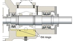
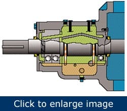
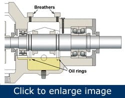
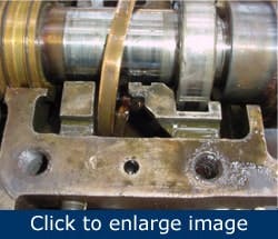
Figure 1. In a typical large-pump bearing housing, two oil rings dip in the oil and fling the lubricant into a slanted trough. The oil runs downhill and enters the bearings. Two limiter screws and two oil ring observation ports are indicated.
In brief:
- Problems in the pump’s drive end might be the cause of repeated failures.
- Bearing protector seals of an appropriate design can promote better bearing lubrication and improve pump reliability.
- The manner in which oil gets to the bearings plays an important role in reliability.
Repeated failures are evidence of undiscovered or unresolved flaws. That said, you should remember that repeat failures can happen only for one of two possible reasons:
- the true root cause of failure remains hidden
- the true root cause is known but isn’t pursued.
Flawed drive-end components in process pumps are little understood, although they contribute to some elusive repeat failures that involve bearings in these fluid movers. Here are some pointers and explanations.
Avoid excessive heat
Figure 2. Two free-running oil rings operate in shaft grooves. Note the required oil return passage at the 6 o’clock radial (left) bearing position. However, the illustration doesn’t show the required oil return passage at the 6 o’clock (right) thrust bearing position. The drawing shows a single limiter screw and two limiter discs.
Some oil-lubricated pumps operating at 3,600 rpm can produce excessive bearing heat if the oil level is set to reach the center of the bearing balls at the 6 o’clock position. Choose a considerably lower oil level to avoid the “plowing effect” of rolling elements that produce frictional power loss and heat. However, with oil lubrication and lowered oil levels, the oil must be lifted and somehow guided into the bearings.
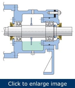
Two choices present themselves: oil rings or slinger rings (Figures 1 and 2) and flinger discs (Figure 3). In the first instance, an oil ring of a given size and weight might have been designed for ISO Viscosity Grade (VG) 32 oil but can’t perform optimally with ISO VG 68. Always be mindful that synthetic ISO VG 32 might be well suited for pumps, whereas a mineral ISO VG 32 lubricant wouldn’t have adequate film strength and film thickness in warmer climates.
Figure 3: A flinger disc is used for lifting oil from the sump. The angular contact thrust bearing set is placed in a cartridge. Upon assembly, this provides an opening of sufficient diameter for the disc to pass through.
Lubricating oil might have to be conveyed or “lifted” from the oil sump into the bearings. Free-running oil rings often are used to do this lifting. However, there are caveats and elusive sources of bearing problems with free-running oil rings.
- An oil ring sometimes leaves its shaft groove path and gets wedged in one of the long limiter screws.
- Oil rings tend to contact a housing’s internal parts if the shaft isn’t truly horizontal. Figure 4 shows an oil ring moving all over the place, probably intermittently touching the inside walls of the bearing housing.
- An oil ring can malfunction unless oil viscosity and oil levels are maintained within a narrow acceptable range.
- Oil ring eccentricity must be maintained within 0.002 in. Bad oil rings can exceed this standard by a factor of 30.\An oil ring shouldn’t distort, which means that it should be manufactured in three stages: (1) pre-machining, (2) stress-relief annealing, (3) finish machining. Cheap oil rings spell trouble.
- There also is sensitivity to bore surface roughness and oil ring bore finish. Both must be approximately 16 to 32 RMS.
Figure 4. Oil rings are sensitive to shaft horizontality and other geometric variables. Markings and measurements can highlight the extent of abrasive wear.
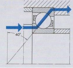
Regardless of the lubrication application method used, additional risk issues should be considered. Many pump thrust bearings use cages (ball separators) that are angularly inclined, and the thrust bearings in figures 1 and 2 are among these. Cages in angular contact bearings can act as small impellers that promote “windage flow” from the smaller toward the larger of the two cage diameters.
There should be an oil return slot (approximately 3/16 in. wide and 1/8 in. deep) at the 6-o’clock position of each bearing housing bore. Verify that these passages exist on any pump that is oil (sump) lubricated. Note that the passage is missing from the thrust bearing side of Figure 2 and from both bearings in Figure 3. Oil getting trapped between the bearing and its housing end cap will overheat.
{pb}Figure 5: Attempts to apply lubricant in the direction of the arrow frequently meet with opposing windage (air flow) from an inclined cage.
Pay particular attention to the impeller-like air flow from an inclined cage (Figure 5). Whatever oil application method you choose, it must overcome windage action that produces pressure differences that impede oil flow.
This risk is further exacerbated if bearing protector seals require pressures surrounding a bearing to be equal. Without such balance, a stagnating pressure rise might exist on one side of the bearing. Drilling suitable balance holes or installing a pressure equalizing bypass can prevent this pressure buildup.
Replacing standard metallic wear rings on impeller eyes and the pump shaft with versions using high-performance polymer, such as Vespel, and modifying the customary impeller eye labyrinth and shaft labyrinth clearances, located behind the impeller, could adversely affect the magnitude and direction of rotor thrust. One of the back-to-back mounted bearings might then be skidding, and the other could be overloaded. Standard bearings won’t perform as expected under those conditions.
[pullquote]If calculations and field measurements confirm skidding and overloading, remedy the situation by installing special sets of preloaded — purposefully not flush-ground — back-to-back bearings. The contact angle in the left-facing bearing of special thrust bearing sets differs from the contact angle in the right-facing bearing. Usually, a 40° angle is selected for the bearing that absorbs the full-speed running load and a 15° angle is picked for the adjacent bearing, which is intended to carry the reverse-direction or ramping-up-to-speed thrust load.
Once a preloaded thrust bearing set is fitted to the pump shaft and the two bearings’ back faces are clamped together properly, the bearings won’t and shouldn’t spin freely.
Bearing protector seals
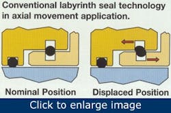
Figure 6: Old-style bearing protector seals with sharp-edged grooves invite a dynamic O-ring to scrape on sharp edges. Shavings then contaminate the lubricant. Also, using only a single O-ring for clamping the rotor to the shaft makes the rotor less stable than if two rings are used for clamping.
Pump bearing housings “breathe,” which means warm air above the liquid oil in a housing expands and will be expelled. Conversely, as the air cools, it contracts and ambient air enters the housing along with water vapor and airborne dust. Eliminating the exchange between the housing’s interior air and the surrounding ambient air can stop the resulting contamination.
In well-designed bearing housings the breather vents should be removed and plugged. Also, install bearing protector seals for risk avoidance. Old-style products might not be avoiding the risk of “pinching” dynamic O-rings (Figure 6).
In essence, modern bearing housing protector seals can improve both life and reliability of rotating equipment by safeguarding lubricating oil cleanliness. However, be aware.
- Bearing protector seals add little value if oil contamination originates with O-ring wear from this very same bearing housing protector seal.
- Bearing housing protector seals are of no help if oil contamination originates with oil ring degradation and if the resulting elastomeric debris gets into the bearings.
- Traditional pressure-unbalanced constant-level lubricators tend to allow air and moisture to intrude through air gaps in these trusted components.
- Pressure-unbalanced constant-level lubricators might be unable to keep the lubricant in the bearing housing at the desired level.
- Lubricant might not reach all bearing components if the bearing housing design fosters windage-related pressure differences. Internal balance holes or equalizing passages generally are needed. The pump manufacturer sometimes overlooks this detail.
Heinz P. Bloch, P.E., is president of Process Machinery Consulting, author of "Practical Lubrication for Industrial Facilities" and "Pump Wisdom," and co-author of “Pump User’s Handbook: Life Extension” and “Oil Mist Lubrication: Practical Applications.” Contact him at [email protected] and (515) 225-0668.
