In the groove: Common myths about mechanical pipe joints
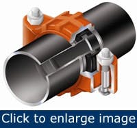
Grooved mechanical pipe joining is a technique pioneered during World War I as a fast, reliable way to transport fuel and water to the Allied troops. It has become a viable joining method on utility and process piping applications when compared with welding, threading and flanging. The mechanical joint, or coupling (Figure 1), has four elements: the grooved pipe, the gasket, the coupling housings and the fasteners. The pipe ends have a cold formed or machined groove that provides an engagement point for the coupling and a sealing surface for the gasket. The gasket seals the pipe ends, trapping fluid within as it is enclosed by the coupling housings. The housings are held together by bolts and nuts tightened with a socket wrench or impact wrench. The coupling housing encases the gasket and engages the circumferential pipe groove to produce a leak-tight seal in a self-restrained pipe joint.
Figure 1. Four elements comprise a mechanical joint: the grooved pipe, the gasket, the coupling housings and the fasteners.
The method has gained widespread use since its invention 85 years ago, but many myths and misunderstandings regarding the grooved joint’s engineering and performance still exist.
The benefits of using a grooved system are plentiful. Rigid and flexible coupling options meet system designers’ needs, a union at every joint allows for ease in system maintenance and retrofit, noise is attenuated as vibrations are reduced at each pipe joint, and the strategic use of sway bracing and rigid/flexible couplings accommodate seismic movements. However, the bottom-line question remains: Is it reliable?
Let’s explore some misconceptions about the grooved mechanical pipe joining method:
- The indent from roll grooving introduces a pressure drop
- The grooving process weakens a pipe and leads to stress failures
- Couplings can’t produce a truly rigid joint and, therefore, the piping system sags over time and requires additional support compared to a welded system.
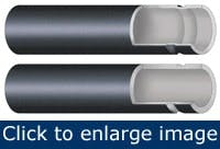
Figure 2. The two types of groove configuration. The roll groove (above) differs slightly from the cut groove (below).
Cut and roll grooving
Some ask how the pipe groove is formed and how that affects the pipe’s performance in different applications. There are two types of grooving: roll grooving and cut grooving (Figure 2).
Used in approximately 90% of grooved piping applications, roll grooving is the most common method. Roll grooving was developed more than 50 years ago for light or thin-wall pipe, which opened the door to a fast, economical method for mechanically joining such pipe. Roll grooving is now used on a wide variety of pipe sizes and wall thicknesses because it’s a fast, efficient and clean pipe end preparation technique without sacrificing pipe joint performance.
Roll grooving displaces a small portion of the pipe wall radially in a cold forming process. The pipe end is placed between the roll set of a grooving machine. The roll set closes, the pipe is compressed and rotated, and a groove is formed around the outside diameter, leaving a circumferential recess on the outside and an indent on the inside.
Roll grooving can be used on Schedule 5 through ANSI standard wall thickness carbon steel and stainless steel, copper, and aluminum pipe or tubing, and up to schedule 80 PVC plastic pipe. Roll-grooved systems range in diameter from 3/4-in. to 60 in. in some materials.
Figure 3. The groove, depicted by the black bar, removes less pipe wall material that threading.
Cut grooving, on the other hand, is commonly used on pipes of ANSI standard wall or greater and for abrasive applications, where the inside of the pipe wall needs to be as smooth as possible to allow materials to pass without obstruction. The smooth, continuous inside surface remains after the groove is cut, making cut grooving suitable for systems that require plastic coating, cement lining or other protective linings for corrosion or abrasion reasons.
Cut grooving involves removal of one-third of the total pipe wall thickness to provide the lip that engages the coupling housing. Cutting a groove removes less material, to less depth, than threading the pipe (Figure 3). Cut grooving can be completed manually or by using motorized tools.
Flow dynamics
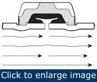
A concern associated with grooved mechanical piping is that the inside diameter indentation of roll grooving will upset the flow dynamics. However, the indentation is small, with smooth edges upstream and downstream (Figure 4). The indentation is at the pipe wall, where fluid velocity is lowest. The pressure drop is so small that it’s considered negligible when compared to other pressure drops, such as those from overall pipe friction, valves, bends and branch connections.
Figure 4. The mechanical joint introduces only a small disturbance to the flow profile.
Flow testing has confirmed that the joints exhibit good flow characteristics. Testing involved grooved and plain-end 4-in. Type K copper tubing, and 2 in. to 8 in. Schedules 10 and 40 carbon steel pipe at flow velocities of 4, 8, 12 and 16 ft./sec. at ambient water temperature.
Pressure taps located 10 ft. apart on a straight section of pipe (or tube) established the baseline measurement at the tested flow rates. Then, the pipe/tube was cut into four segments to insert three roll-grooved pipe joints between the pressure taps. After the new pressure losses were recorded, the baseline loss was subtracted out to determine the insertion loss. The average loss of each grooved coupling joint was about 1/2 equivalent feet of pipe.
Additional independent testing by Factory Mutual Research Corp. supports these findings. Factory Mutual’s Loss Prevention Data Technical Advisory Bulletin 2-8N stipulates that one equivalent foot of pipe be added for each roll-grooved joint on any pipe size. This is conservatively higher than actual test values, yet still relatively low compared to the values established for components such as valves and fittings. These values further attest to the low loss characteristics of roll grooved joints.
Roll grooving pressure drop is consistent and can be accounted for during system design. Although, in theory, welded systems produce little to no loss at the joints, variables of craftsmanship can lead to welding material entering the pipeline, interfering with flow and, in some cases, dislodging and causing a system blockage.
Pipe stress
Another concern is the ability of a grooved joint to perform adequately under load. Regardless of pipe joint type, a pipe under load exhibits two forms of stress: longitudinal and hoop. Longitudinal stress is a tensile stress, tending to stretch the pipe axially. A failure from longitudinal stress produces a circumferential fracture. Hoop stress is “ballooning,” a radial expansion, and the potential failure mode is a lengthwise split. The calculations for determining stress also show that the hoop stress will be twice longitudinal stress:
Hoop stress = (P x OD) / (2 x Tw)
Longitudinal stress = (P x OD) / (4 x Tw),
P is the line pressure, OD is the outside diameter and Tw is the wall thickness. This means that overstress failures are most likely to occur along the length of the pipe — in a weld seam, for example — not on the pipe circumference.
Everything else being equal, a decrease in wall thickness results in an increase in hoop stress. In a grooved joint, the coupling housing, which engages the groove, prevents diametric expansion and reinforces the pipe. This suggests the grooved technique doesn’t produce greater hoop stress and, therefore, doesn’t weaken the pipe. Any potential increase in pipe hardness, reduction in tensile strength or reduction in elongation the roll grooving process produces has no effect on the pressure capability of the joint, and pipe material changes are comparable to any other cold-forming manufacturing operations.
Cut grooving reduces the wall thickness by removing a narrow circumferential strip of material from the outside surface. The hoop stress remains approximately the same because the groove is narrow and reinforced by the full wall thickness of pipe on either side of the groove. The groove also is reinforced by the coupling key engaged in the groove, preventing it from expanding diametrically. However, the longitudinal stress increases proportionally with the decrease in the wall thickness. Therefore, if one half of the original wall thickness remains, longitudinal stress is doubled or approximately equal to the hoop stress.
Because the cut groove depth in standard wall thickness pipe removes only about one-third the original pipe wall thickness, the hoop stress remains larger than the longitudinal stress. Any over-stress failure continues to occur along the length of the pipe, not at the groove, demonstrating that the groove area isn’t weaker than the longitudinal barrel of the pipe. Again, this means that the groove doesn’t compromise joint strength.
The pressure rating on a grooved mechanical pipe joint is determined in consideration of all the components involved. Grooved pipe has no rating without the corresponding coupling, and coupling ratings are a function of the piping material and wall thickness. Every manufacturer’s published pipe joint rating is calculated or tested on pipe that contains a groove, meaning that any potential effect of the groove on the strength of the pipe is incorporated in to the coupling’s performance rating.
Rigid versus flexible systems
Another misconception about grooved mechanical pipe joining is that couplings can’t produce rigid joints and require extra supports to prevent system sagging. The housing on a rigid coupling positively clamps the pipe to produce a rigid joint, providing system behavior characteristics similar to those of other rigid systems. The piping remains aligned and isn’t subject to axial movement or angular deflection.
Systems using rigid couplings need support techniques identical to those of welded systems when designed and installed according to the hanger spacing requirements as noted in the ASME B31.1 Power Piping Code, ASME B31.9 Building Services Piping Code and NFPA 13 Sprinkler Systems Code.
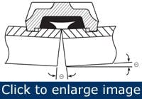
Figure 5. Innate joint flexibility allows smaller thermal expansion loops.
In most utility and process systems, temperature fluctuation produces dimensional changes, stress and potentially damaging forces. Flexible couplings accommodate the thermal effects by allowing for linear movement and deflection (Figure 5). A series of flexible couplings in close proximity accommodates as much as 3 in. (76mm) of linear movement. Flexible couplings can be used at changes in directions to provide stress-free offsets, or on “traditional” expansion loops. However, by using flexible couplings at the elbows of the expansion loops, the loop may be reduced in size one-half to one-third the size of a loop of welded construction.
Proven reliability
The ultimate objective, reliability in a mechanical grooved pipe joining, has been proven through research, testing and extensive evaluation. It has stood the test of time in some of the most demanding industrial applications, including power generation, primary and secondary oil production, Canadian oil sands high-pressure piping, biofuel production and water system technologies, including reverse osmosis and nanofiltration. Furthermore, it has been a reliable component of mission-critical applications such as data centers, flammable chemical cleaning applications, locomotive engine fuel and cooling lines and in hydraulic elevator services.
Mechanical joints are used in a variety of industrial piping services, including utility and process piping. However, they are not appropriate for all circumstances. Grooved mechanical couplings, like all joining methods and materials, have limitations. These limitations include excessively high and low temperature extremes, excessively high pressures and chemical compatibility of the elastomeric seal with various chemical services. It is recommended to consult the manufacturer’s Web site, published literature or technical department when questions arise about specific services and product performance.
Engineers, contractors and owners can be assured that grooved piping technology has been thoroughly tested, both in research and in the field, and has demonstrated consistent strength and reliability. Myths about the process, system rigidity, elasticity and stress, and the flow characteristics are easily explained. When the versatile and economic nature of the method is considered, it’s clear that when appropriate, grooved mechanical pipe joining can and should be the preferred choice.
Gary Trinker is manager of engineering services at Victaulic Co., Easton, Pa. Contact him at [email protected] and (610) 559-3300.

