Industrial plants throughout the world rely on critical fans for operation, but what happens when a fan rotor, rotating at a peripheral speed of 450 miles per hour, fractures?
The scene looks something like this: Pieces of the wheel rip away from the rotor, tear through the fan housing and fly off. The steel shaft bends and twists like a pretzel. The cast iron bearing housings break apart. The motor separates from its pedestal and lands on the foundation. The plant is shut down, and it takes weeks to clean up the mess, rebuild the fan housing and install a spare rotor (assuming the plant has one on hand).
This scenario has been played out in heavy industrial facilities worldwide. What are the causes of this situation? What steps can maintenance personnel and engineers take to minimize the chances of such a catastrophic failure?
Before we address what you can do to prevent fan failure, consider the real-world examples below when making a case for preventive action.
Coal dryer induced-draft fan
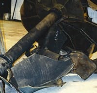
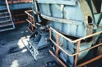
A 96 in.-diameter centrifugal fan had been in service for about three years on a coal dryer application in West Virginia. The fan operated at 1,180 rpm with a peripheral speed of 337 mph. Although there was an upstream cyclone separator to provide gas cleaning, some coal dust continually passed through the rotor. Erosion-resistant liners protected the fan wheel, but small particles of coal dust entrained in the high-velocity gas stream slowly eroded the unprotected welds at the edges of those liners. There was no planned inspection of the rotor and no routine monitoring of the bearing vibration. One morning, minutes after fan startup, the rotor ripped apart, completely destroying the fan and damaging nearby equipment. Fortunately, no operators were in the area. The plant was shut down for nearly three weeks while a new fan was fabricated and installed on an emergency basis (Figures 1 and 2).
This is the impeller from coal dryer fan following a catastrophic failure.
Foundry gas-cleaning induced-draft fan
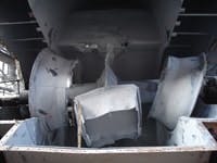
This 88 in.-diameter, double-inlet, variable-speed centrifugal fan was operating at about 350°F. The operators noticed some increase in the noise and vibration at certain speeds, but once the fan changed speeds, the vibration seemed to subside a little, easing their concerns. The fan had no bearing temperature or vibration-monitoring equipment installed, and periodic vibration monitoring was spotty. The blades generated a pressure pulse when they passed the “cutoff” of the scroll-type centrifugal fan housing. The operators didn’t realize that at certain speeds, the fan’s blade passage frequency (and the resulting frequency of pressure pulsations) caused excitations that exactly matched the natural frequencies of some of the fan rotor components. The result was higher-than-expected deflection and stress levels. This caused high-cycle fatigue cracking of the rotor material near the toe of several fillet welds. Left undetected, the cracks propagated until they reached a critical crack length. Without warning, the crack growth rate increased dramatically, and the fan wheel flew apart (Figure 3).
Rotor failure damaged the fan housing and bearings.
These two examples demonstrate the significant effects that axial and centrifugal fan rotor failure can have on plant operation and worker safety. In addition to the obvious damage and plant downtime, similar situations have resulted in severe injury — and even death — of workers near the fan when it failed. So what can maintenance personnel do to protect operations and workers from catastrophic failures?
Continuous monitoring is your best protection
This 88-in. centrifugal fan shows the results
of a rotor fatigue crack failure.
Preventive and predictive maintenance using frequent visual inspections, nondestructive testing of welds and periodic measurement of bearing vibration help, but these techniques alone can’t effectively prevent sudden and catastrophic failures like those described above. The best approach is continuous monitoring of vibration and bearing temperatures with the instrument signals linked to a fast-response automatic fan shutdown control. Here’s why:
- If erosion is a possibility, thinning structural components subjected to the high stress resulting from centrifugal forces can suddenly reach a failure point.
- Once fatigue cracks have been initiated, they can propagate faster and faster until there is a sudden, unpredicted failure.
Routine visual inspections, including nondestructive testing aids such as magnetic-particle, dye-penetrant or fluorescent-particle techniques, are helpful in establishing the presence of cracks, but these inspections can’t be done continuously during operation.
Similarly, predictive maintenance vibration monitoring is effective for establishing a baseline and determining dangerous trends (or step-changes) in vibration levels, but it can’t always protect against the risk of sudden and catastrophic failure.
Monitoring fans with rolling-element bearings
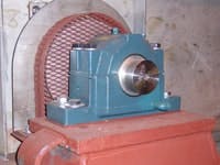
Many fans have rolling-element bearings, either single-row-deep-groove ball bearings or spherical roller bearings (Figure 4).
This typical rolling-element bearing is a prime candidate for online vibration sensors.
These bearings have a direct mechanical link from the shaft, through the rolling elements and the races, to the bearing housing. Therefore, for these bearings, it’s best to mount seismic probes on the bearing base (or better, mount directly to the fan bearing housing), to monitor the bearing housing vibration level. These seismic vibration pick-ups are available as:
- Accelerometers, which measure vibration in acceleration units, typically Gs
- Velocity pick-ups, which measure vibration in velocity units, typically in./sec. or mm/sec.
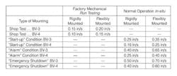
Using velocity output units, the recommended alarm and shutdown vibration levels are independent of the shaft operating speed. Therefore, regardless of which type of seismic probe you use, the output usually is converted to velocity units for monitoring and recording vibration levels. Suggested vibration limits are specified in ANSI/AMCA Standard 204, “Balance Quality and Vibration levels for Fans.” In this standard, fans are categorized over a wide range of applications and motor sizes. For most industrial applications, balance-vibration categories BV-3 and BV-4 apply. The maximum recommended vibration levels (peak velocity, in./sec.) in these are shown in Table 1
Notes:
• Alarm: Action should be taken immediately to determine the cause of the high vibration and to take steps to correct it.
• Shutdown: The fan should be shut down immediately.
• Rigidly mounted: A fan mounted by means of anchor bolts and epoxy grout on a heavy concrete foundation in a properly prepared soil or bedrock; fan operates well below the system first natural frequency.
• Flexibly mounted: A fan mounted on elevated structural steel or on a spring-isolation system; fan operates well above the system first natural frequency.
Monitoring fans with sleeve-type bearings
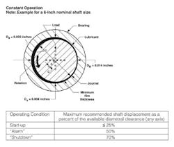
Many larger fans use hydrodynamic sleeve-type bearings, such as plane cylindrical bore, elliptical bore and tilting pad units. The rotating shaft rides on a thin film of oil inside the bearing liners. Typically, the bearing housings are robust with high rigidity and are mounted on equally rigid steel pedestals or concrete piers. Significant bearing housing vibration requires a tremendous amount of vibratory force. Therefore, when these bearings are used, monitor the shaft vibration, as opposed to the bearing housing movement. This can be done by means of eddy-current proximity probe systems. The probes are mounted into the bearing housings, a clean environment that protects the proximity probes against dust and corrosion. These systems monitor the distance between the rotating shaft surface and the probe tip, and the output is the relative motion between the shaft surface and the bearing housing. Of course, the shaft surface quality, diameter and eccentricity must be closely controlled during fabrication so that the output accurately reflects the shaft vibration and not the shaft’s out-of-round condition.
Typically the output is in displacement units (mils peak-to-peak or mm peak-to-peak). ANSI/AMCA Standard 204 includes the recommended maximum displacement of the shaft relative to the available clearance from the bearing line.
Shaft movement should remain within the limits established by ANSI/AMCA Standard 204.
On the other hand
We’ve seen examples of what can go wrong in the absence of preventive and predictive maintenance. Here’s an example of what goes right when plants use vibration monitoring.
A 7,500-hp induced-draft fan on a cement kiln was subject to erosion because of particulates passing through the fan. After welds at the edges of the liners began to erode, a portion of a blade liner — weighing 50 lbs — loosened, then broke off while the rotor tip speed was about 430 miles per hour. One might expect that the tremendous unbalance forces would cause severe damage.
Although the force of the 50-lb piece ruined the fan housing inspection door, there was no other damage to the fan housing, fan shaft, bearings, coupling or motor. The vibration monitoring system installed on the fan bearings sensed the higher vibration developing as the blade liner began to loosen. The system was interlocked to the fan motor and shut the fan and system down immediately. No plant operator would have been able to react to this situation so quickly. This is an excellent example of the value of continuous vibration monitoring that is interlocked to the main fan motor-driver and is set up for instant response if the vibration exceeds a preset shutdown level.
Industrial fans that are subject to erosion, corrosion or elevated temperatures often are at risk of catastrophic failure. Rotating equipment, even clean-air fans, are still subject to fatigue-related failures. A visual inspection of the fan rotor combined with nondestructive testing of rotor welds is an important step that minimizes the chance of a sudden failure. Periodic measurement of vibration levels with historical trend records reviewed and analyzed also can be helpful in preventing such failures. No system can absolutely eliminate the risk of failure, but continuous vibration monitoring combined with a fast-response shutdown system offers the best protection.
Les Gutzwiller is vice president of Technical Services, Robinson Industries Inc., Harmony, Pa. E-mail him at [email protected] and (724) 452-6121.
Figures: Robinson Industries, Inc.

