The role of electrical signature analysis in predictive maintenance
Many manufacturing companies have a lot of time and money invested in rotating equipment. They recognize that to protect their investment and achieve efficient, cost-effective operations they must keep these machines operating at maximum capability, which is accomplished by performing regular machine maintenance. Most machine maintenance falls under one of three maintenance philosophies: run to failure (RTF), preventive (PM) or predictive (PdM).
The most expensive method of performing maintenance is RTF, as it usually results in additional, and sometimes catastrophic, machine damage. Allowing the machine to operate until the bearings collapse could damage the shaft, wear the bearing housing, rub the impellers or worse. Additionally, the parts that usually fail aren’t typically stored in spares inventory. They carry a premium price and involve extremely high shipping and transportation costs just to get the necessary parts on-site. Add to that the cost of labor required to return these damaged machines to operating condition and it's easy to see how operating a maintenance program as RTF is the most costly of the maintenance philosophies.
The preventive maintenance philosophy is based on the premise that most failures are age-related and, by conducting minimal maintenance tasks at predetermined time intervals can prevent many catastrophic failures. Detailed studies have been conducted to determine the mean time between failure (MTBF), with maintenance tasks and intervals developed accordingly. In the mid-1980s, a reliability study determined that only 11% of failures were age-related, whereas 89% were random. In fact, 68% of failures occur either immediately after installation or after returning from maintenance, indicating that the failure probability actually increases by performing maintenance tasks under the preventive method. Also, the probability of failures increases with the complexity of the machine.
Figure 1. Easy-to-use tools, because they identify a problem, its cause, and a correction, have put electrical reliability at the forefront in most plant reliability programs.
The predictive maintenance (PdM) practice takes non-destructive measurements during a machine's operation to determine the machine’s condition. Use of this practice received a jolt with the introduction of the data collector in the mid-1980s. Predictive maintenance technologies perform standard “non-specific or specialized” measurements, and are generally non-invasive and easy to use. Predictive maintenance consists of three phases: detection, analysis and correction.
The detection phase identifies a problem machine by screening as many machines as rapidly as possible. Once the detection phase identifies a bad machine, the analysis phase is implemented. This phase might require additional measurements, tests or technologies, and is similar to getting a check-up by a doctor. The general practitioner does the initial screening, and if additional tests are required, specialists are called in. Once the problem is analyzed properly, the correction phase is implemented.
Many PdM programs fail because they omit the important analysis phase, or they attempt to take too much data during the detection phase. Going from detection phase to correction phase, leaving out the analysis phase, is analogous to having open-heart surgery because of high blood pressure. Furthermore, if the corrective action is based solely on the data taken to identify a bad machine (detection data), often the wrong corrective action is taken, wasting resources and losing credibility for the program.
Conversely, if too much data is taken during the detection process, valuable time is wasted unnecessarily. This limits the number of machines that can be monitored during each route and requires additional labor to survey the entire plant completely. This means some machines don’t get surveyed, and in a typical mature PdM program, it’s estimated that 2-3% of new problems are detected during each data collection route. Often, post-mortem forensics of a failed machine reveal that sufficient data had been taken to identify the problem, but the data had not been reviewed and, consequently, the developing fault was missed.
Procedures for the correction phase can range from continued monitoring at reduced intervals to a complete disassembly and rebuild. Therefore, the key to an effective, less costly, correction phase is accurate, thorough procedures during the analysis phase.
Electrical reliability
[pullquote]Today there might be several generating stations sending power to the grid supplying your facility. The power might travel through many different transmission paths and across several municipalities or distribution districts before reaching the plant. There are currently 50 different power quality standards in the United States, one for each state, and yet power supplies aren’t restricted to state boundaries. The bottom line is that the quality of the power used to drive a plant's multiple machine motors can vary.
Some plants routinely monitor incoming power but routinely don’t check the quality of the power delivered to the motor at the motor control center (MCC). A 2% voltage unbalance in the motor control center can generate as much as a 20% current unbalance within the motor, and this unbalance produces circulating currents within the motor. The circulating currents, in turn, result in excessive heat generation within the winding and eventual insulation breakdown, leading to a catastrophic failure of the motor winding.
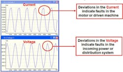
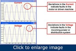
Figure 2. Deviations from the incoming voltage are reflected in the motor current. However, if a fault in the motor system is caused by the motor or the driven machine, these fault frequencies are in the current spectrum, but not in the voltage spectrum.
Precision maintenance
Precision maintenance takes predictive maintenance to the next level by identifying the problem, as well as the cause and likely solution. Electrical reliability can be affected adversely by any component in the motor system, which includes the motor, the power distribution system, the mechanical coupling, the mechanical load, the process and starting, control and drive systems. The motor consists of motor windings, stator and rotor iron, cabling and connections to the motor. Most users look at motor systems from the component level, trying to evaluate or troubleshoot individual aspects of the larger system. However, a systems approach to maintenance looks at the reliability of the entire system and component relationships and synergy.
Figure 3. A bbroken rotor bar produces an open in the rotor circuit and current can’t flow through the broken bars. When broken rotors bars are under magnetic field poles, the bars located 180 degrees away to allow current flow, producing a dead spot on the rotor.
ESA uses algorithms to identify both electrical and mechanical faults in the motor and mechanical faults in the driven machine. In addition to finding mechanical faults, ESA performs a survey of the motor systems power quality. Like machine vibration analysis, ESA performs a Fast Fourier Transform on the input voltage and current waveforms of the motor to determine the content of their respective frequencies. If the spectral peak is in the current waveform only, the fault is in the motor or the driven machine. However, if it’s in both the voltage and current spectrums, the fault is traced to the incoming power. ESA can positively identify stator faults, such as loose windings or a loose stator iron, as well as motor assembly faults that cause unbalanced magnetic fields, including distortions of the stator magnetic field, or rotors that aren’t centered in the magnetic field. ESA also identifies other mechanical problems in the motor such as the condition of the rolling element bearing or the balance or alignment of the rotor system. In addition, faults in the coupling system, such as loose or cracked belts or gear problems, also can be identified automatically using ESA.
The key to signature analysis is identifying frequency content of the input signal and correlating these frequencies to the operating condition and design of the machine.
ESA uses the change in the air gap between the rotor and the stator or changes in current to indicate faults in the motor system. If either the air gap inside the motor or the load on the motor changes, the motor current will change. Periodic events, such as vane passing frequency, causes the motor current to modulate at the frequency of the event.
An eccentric rotor occurs if the shaft isn’t centered in the rotor core, or if the rotor core is not perfectly round. This produces rotating narrow clearances inside the stator, which unbalances the magnetic forces inside the stator as the shaft rotates. This is referred to as dynamic eccentricity. When the rotor is eccentric, it produces a narrow clearance between the rotor and stator that disrupts the magnetic fields current flow through the rotor bars produces. Because the eccentric rotor narrows the clearance between the rotor and the stator, the rotating magnetic field causes the rotor bar magnetic fields to modulate at a frequency equal to the number of poles times slip speed. ESA can detect very small rotor eccentricities that will result in premature motor failure.
Motor faults classified as "stator mechanical" are caused either by loose windings in the stator slots or a loose stator core in the motor enclosure. A rotating magnetic field passing the loose component can displace it. This movement, in turn, disrupts the magnetic fields surrounding the discontinuities in the stator iron. If either the stator iron is loose in the enclosure or the windings are loose in the slots, the magnetic fluxes surrounding the stator slots modulate at line frequency as the magnetic field rotates around the stator. This produces line frequency sidebands around the stator slot passing frequency in the FFT. If this condition continues, the insulation in the slots will wear away and result in either winding shorts or ground faults.
Static eccentricity occurs when the rotor isn’t centered in the stator, or if the stator magnetic field isn’t perfectly round (non-concentric or eccentric). If the stator magnetic field is eccentric, then, at some point in the air gap, the rotor magnetic field will be closer to the stator magnetic field than any other point. Either of these cases will produces an electrical unbalance in the motor air gap that pulls the rotor toward the stator as the rotating magnetic field passes by the narrow clearance.
Figure 4. Dynamic eccentricity can produce excessive force on the rotor and stator. Continued operation in this condition will result in premature rotor and/or bearing failure.
These forces might not be enough to cause the motion to be measured at the bearing housing, but they’re sufficient to decrease the lube oil thickness as well as produce torsional forces acting on the rotor motion. Reducing the lube oil thickness exponentially reduces bearing life, whereas the torsional forces applied to the rotor eventually lead to loose and broken rotor bars. Experience has shown that many rotor bar failures are preceded by a history of static eccentricity.
Broken rotor bars can be the result of either assembly error or thermal stresses and, when they fail, they generally do so in groups. Normally, rotor bars break at the point they connect to the shorting ring or end ring, increasing starting current and reducing full-load torque and full-load speed. Additionally, the rotating force produced by the rotation causes the broken rotor bar to pull outward toward the stator iron. This can cause the rotor bar to come into close proximity of the stator iron and might result in arcing from the rotor due to the current generated in the rotor bars shorting to ground. If the rotor bar contacts the stator iron mechanically, it can cause physical damage to both the rotor and stator iron. This type of failure can occur instantaneously and result in total motor destruction.
William Kruger is technical and training manager at All-Test Pro. Contact him at [email protected] or (800) 952-8776.


