Already common in HVAC, pumping and industrial automation systems, the use of variable-frequency drives (VFDs) is growing. VFDs are smaller and more powerful, more reliable, easier to program and less expensive than ever. But, VFD/motor systems must be designed for reliability and trouble-free operation to keep the energy savings, which can reach 20% or more, from being wiped out by a system failure.
VFDs can induce electric currents on motor shafts that ruin bearings, shorten motor life and diminish system reliability. One way to mitigate the effects of these currents is to ground the motor shaft to protect bearings and eliminate expensive repairs.
Energy-saving potential
The VFD converts line power to direct current and filters it to smooth the waveform. A pulse-width-modulation inverter turns the DC back to AC, but now in variable form. The typical output frequency, also called the carrier or switch frequency, is between 2 kHz and 12 kHz.
[pullquote]VFDs that drive motors directly in constant-torque applications avoid using any more power than necessary. With encoder feedback, a VFD also can control motor speed.
Regardless of the application, engineers who select the VFD should understand the entire system, including the possible current paths. A pulse-width-modulated waveform has high-frequency components (harmonics) that are coupled capacitively to the motor shaft and can discharge through the bearings. Even inverter-duty motors are vulnerable to bearing failure from VFD-induced currents.
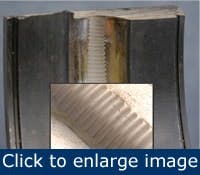
These currents can cause pitting, fusion craters and “fluting” (Figure 1). This electrical-discharge machining leads to bearing noise, premature bearing failure and motor failure. There is considerable evidence to prove that VFD-induced bearing damage is a large and growing problem. Consider:
Figure 1. Fluting is a problem that sparking inside a bearing can promote.
Other problems appear if the motor isn’t designed for use with a VFD, or if the motor or VFD are mismatched to the load. For example, when maintaining constant torque, a motor loses efficiency and runs hotter at lower speeds (but hotter still when controlled by a VFD). If the motor is operated at less than 30% of maximum speed, it might need extra cooling or thermal protection.
Similarly, a VFD-controlled motor’s torque may drop more quickly at lower speeds than when using pure sine-wave power. For constant-torque loads, a VFD should be rated for 60 seconds at 150% of the load. A VFD’s current rating also limits the load-acceleration rate.
The cable connecting a VFD with a motor shouldn’t exceed 50 ft. total length to avoid standing waves that meet at the motor terminals, in effect doubling the voltage to the motor. If a longer cable is required, use additional line filtering to protect the motor and other nearby sensitive equipment from harmonic content and radio-frequency interference (RFI). RFI also can be reduced by enclosing motor leads in a rigid conduit. Regardless of length, the cable between a VFD and the motor it regulates can be enclosed in a corrugated aluminum sheath or another kind of grounded, low-impedance shielding.
VFDs might not be appropriate for pumps that maintain high pressure. During periods of low flow, the motor might not be able to slow down enough while maintaining pressure. VFDs that shunt excess energy from the DC bus can be used in systems that require dynamic braking.
Look at bearing damage
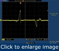
Figure 2. An oscilloscope trace reveals the presence of pulsing shaft currents.
Short of dismantling the motor, there are two ways to check for bearing damage from induced shaft currents: measuring either voltage or vibration to look for energy spikes in the range of 2 kHz to 4 kHz. Both methods require special equipment and experienced personnel to conduct tests and analyze the results. Both are best used early on to establish a baseline and to monitor trends later. Neither method is foolproof.
By the time a vibration test confirms bearing damage, it usually has reached the “fluting” stage. Likewise, the main benefit of a voltage test might be the relief it provides when the results indicate no bearing damage. If a baseline voltage measurement is taken when a VFD is installed, successive tests might provide early warning of harmful current loops. But, there are many variables — predicting bearing damage is not an exact science.
{pb}Induced shaft currents, which are sometimes called common-mode voltage, can be measured by touching an oscilloscope probe to the shaft while the motor is running (Figure 2).
Rotor voltages build to a threshold before discharging in short bursts along the path of least resistance to the frame (ground), which all too often runs through the bearings. Serious bearing damage is thought to be more likely in systems that have a high carrier frequency, a constant speed or inadequate grounding. A high carrier frequency means a high discharge rate. For this reason, use a VFD that permits fine tuning of the carrier frequency in increments of no more than 1 kHz. In general, it’s advisable to keep the VFD output frequency below 6 kHz.
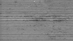
Figure 3. Normal minimal wear from ball-race contact.
There’s some debate about whether constant-speed operation makes VFD-controlled motors more vulnerable to electrical bearing damage. Obviously, the question is moot because VFDs are seldom used in constant-speed applications. There’s no doubt that inadequate grounding increases the possibility of bearing damage. Viewed under a scanning electron microscope, a new bearing race wall is a relatively smooth surface. As the motor runs, ball bearings form tracks in the wall. With no electrical discharge, the wall is marked only by this mechanical wear (Figure 3). Without proper grounding, electrical discharges can quickly scar the race wall.
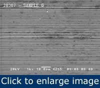
During every VFD cycle, these discharges leave small fusion craters in ball bearings and the bearing race wall. Before long, the bearing race becomes riddled with pits known as frosting (Figure 4). The damage leads to noisy bearings, but by the time the noise is noticeable, bearing failure often is imminent. Because many motors have sealed bearings, electrical damage has become the most common cause of bearing failure in VFD-controlled AC motors.
Figure 4. The phenomenon known as frosting is caused by electrical discharge that forms small craters inside the bearing.
In the phenomenon called fluting, the VFD’s frequency causes concentrated pitting at regular intervals along the bearing race wall, forming washboard-like ridges. Fluting can cause excessive noise and vibration. In an HVAC system, the noise might be magnified and transmitted throughout the building via ductwork.
Mitigating damage
Electrical damage to motor bearings often begins at startup and grows progressively worse. The induced current must be diverted from the bearings by means of insulation, shielding or an alternate path to ground. These technologies vary in terms of cost and effectiveness.
Insulating the motor bearings often shifts the problem elsewhere. Blocked by insulation, shaft current seeks the next easiest path to ground. Attached equipment, such as a pump, often provides this path and takes on bearing damage of its own. Insulation is subject to contamination and might be self-defeating. In certain circumstances, the insulating layer exhibits a capacitive effect on high-frequency, VFD-induced currents, allowing them to pass right through to the bearings it was supposed to protect.
A Faraday shield — grounded conductive material such as copper foil or paint between the stator and rotor — can be installed. If built to the proper specifications for the motor, this can block most of the harmful currents that jump across the motor’s air gap. However, this measure often is difficult to implement, and attached equipment could still be vulnerable to deflected currents. Nonconductive ceramic ball bearings divert currents from the motor’s main bearings, but might leave attached equipment open to damage of its own. Ceramic bearings can be costly and might have to be resized to handle static and dynamic mechanical loads.
Another approach uses conductive grease, which, in theory, bleeds off harmful currents by providing a lower-impedance path through the bearings. In practice, however, the conductive particles in the grease can increase mechanical wear. Metal grounding brushes that contact the motor shaft to provide alternate paths to ground certainly help. Unfortunately, they also wear and corrode, thus requiring regular maintenance.
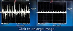
Alternate discharge paths to ground, when properly implemented, are preferable to insulation because they neutralize shaft current. Techniques range in cost and sometimes can only be applied selectively, depending on motor size or application. A viable solution would provide an effective, low-cost, very-low-resistance path from shaft to frame, and could be applied broadly across all VFD/AC motor applications. A grounding ring with conductive microfibers meets these criteria. It uses the principles of ionization to boost the electron-transfer rate and promote extremely efficient discharge of the high-frequency shaft currents that VFDs induce (Figure 5).
Figure 5. Without some form of mitigation, VFD-induced shaft currents (shown on left oscilloscope screen) can cause damage. The screen on the right demonstrates how effectively the microfiber ring reduces these currents by channeling them safely to ground.
The technology is scalable to any NEMA or IEC motor regardless of shaft size, horsepower or application. The rings have been applied to power generators, gas turbines, AC traction and brake motors, cleanrooms, HVAC systems and a long list of other industrial and commercial applications.
For VFD-equipped motors of less than 100 hp (75 kW) and shaft diameters below two inches (50 millimeters), a single ring on the drive end of the motor shaft, the preferred location, is typically sufficient to divert harmful shaft currents.
Large AC motors (100 hp/75 kW or more) and even large DC motors, especially those with shaft diameters greater than two inches (50 millimeters), are more likely to have high-frequency circulating currents (as well as EDM-type discharges) that can damage bearings. Motors with roller bearings also are vulnerable to damaging currents because roller bearings have a greater surface area and a thinner lubricant layer. Such applications benefit from the combination of a microfiber ring on the drive end and insulation on the other end. This also might be the solution in situations where installing a ring on the non-drive end would be impractical because of encoders, fans or other special circumstances. This also is a common solution for motors above 500 hp (375 kW), and most manufacturers already use this approach. However, when insulation on the drive end isn’t designed into the motor or can’t be installed easily, two microfiber rings might suffice. In critical applications where motors have ceramic bearings, at least one ring should be used to ensure that shaft voltage doesn’t pass to other equipment.
The rings are available in two versions: a full-circle design for most NEMA- and IEC-frame motors and a split-ring design that allows field installation on larger shafts without the need to disassemble equipment. A mounting adaptor facilitates installation on motors with shaft shoulders, slingers, bearing caps or end-bell protrusions.
Maintenance issues
Once installed, the rings require no maintenance. Unlike conventional shaft-grounding brushes, the nearly frictionless conductive microfibers cause no wear; are unaffected by dirt, grease or other contaminants; and last for the life of the motor regardless of speed. Test results show surface wear of less than 1 mil per 10,000 hours of continuous operation and no fiber breakage after 25 million direction reversals.
Adam Willwerth is development manager for Electro Static Technology, Mechanic Falls, Maine. Contact him at [email protected] and (207) 998-5140.
