Considerations for using bypass contactors with VFDs
People in industry are continually finding applications that benefit from variable frequency drives (VFDs), which allow users to adapt or change their process to provide a more efficient outcome, usually in terms of production.
For example, take a simple conveyor that carries a product to a boxing machine or a palletizer. Without VFDs, this process will be dedicated to the predetermined base speed defined by the motor’s nameplate rpm, the gearbox ratio, and the diameter of the driven sprockets. Imagine what would happen if the speed of all of the motors could be increased by 10% or adjusted up or down to meet the limitations of the equipment downstream. In another application, a process that depends on pressure or flow may require an operator to watch gauges to start and stop a machine to prevent overspeed or underspeed conditions that negatively affect overall efficiency. A VFD wired into a transducer used for PID (proportional, integral, derivative) feedback would adjust its own speed based on predefined setpoints.
In addition, a VFD can provide the benefits of a soft start, using an acceleration period from zero speed up to the target range that decreases the damage to mechanical equipment such as gearboxes and chains. Suppose an employee is sick or working on another line—the entire machine can be slowed down to meet the limitations of the remaining workforce.
However, when considering whether and how to deploy VFDs, it is also critical to consider the role of the Bypass contactor. These contactors ensure continued motor operation at full speed in the case of VFD failure or emergency service. This article looks at the factors that go into determining whether a plant should (a) completely switch from across-the-line contactors to VFDs; or (b) keep both, thereby providing a backup system that can prevent a total production shutdown.
VFD deployment and choice of backup system
One of the first steps in deploying VFDs is to make a list of existing equipment that is powered by electric motors. Next, working with maintenance and production, identify which of this equipment would benefit from variable speed. Keep in mind that a production line with multiple motors may require a VFD on each. Increased production, efficiency, and the availability of motor feedback regarding current, speed and related items will also add to the positive column.
Once VFDs are installed and operating, it may be desired to have a backup system for motors and processes that would cause issues if they came to a complete and unpredicted stop. For motors that previously ran on contactors alone, the old control system may be kept in case of a VFD failure. On new systems, a study may be required to determine which VFDs are critical to proper operation and which backup system is best for each VFD.
Next, the parameters must be defined on how and when to enable the system to change from VFD mode to bypass mode and back. This could be as simple as tying an automatic transfer to a fault relay in the VFD. An alternate option would be to wire the VFD fault relay or the transducers into a PLC, where predefined parameters will dictate when and where to make this switch.
In the case of an automatic change from VFD mode back to across-the-line contactors, the change can cause problems with product quality or even jeopardize operator safety. One useful tool in these cases would be to install pilot lights that could indicate that a VFD has detected a problem and tripped out. Once alerted by the pilot light, an operator or maintenance technician could analyze the situation, determine if it is safe and necessary to continue, and manually transfer operation from VFD mode to bypass mode.
Switching to Bypass contactors also may result in a disruption to normal production processes, thereby impacting product quality. In these cases, plant engineers should pre-define the process tolerance levels for acceptable finished product. It may also be important for operators, maintenance or engineering personnel to know that VFD mode has changed to bypass mode, so the cause of the change can be investigated or corrected. This could be accomplished through pilot lights on the VFD cabinet, pop-ups on an HMI screen, or notifications to cell phones.
In some cases, an automatic change from VFD mode back to across-the-line contactors would cause problems with quality or even jeopardize operator safety. For these, pilot lights could indicate that a VFD has detected a problem and tripped out. These scenarios may require an operator or maintenance person to analyze the situation, determine if it is safe and necessary to continue, and manually transfer operation from VFD mode to bypass mode.
All systems modified to include a bypass mode must also be tested to make sure that as many types of failure modes as possible can be identified. They must also ensure that what happens when the VFD is taken offline and replaced by contactors is clearly defined and understood.
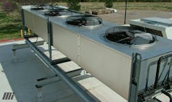
When Bypass contactors are used for multi-motor applications in conjunction with VFDs, certain parameters often define the switching modes. For example, if the setpoints are not properly evaluated in a pressure-related HVAC system, motor contactors may be staged on and off, even when the VFD is in operation. Each time a motor contactor drops out, a spike will go down the power line, which could damage the VFD’s output transistors and lead to early failure. When the same contactor that was turned off suddenly pulls in, and the VFD is running at a higher frequency closer to the maximum voltage level, the resulting instantaneous current draw due to inrush could result in an overload or high current trip.
Regardless of which type of bypass is implemented, all systems modified to include a bypass mode must also be tested to make sure that as many types of failure modes as possible can be identified. They must also ensure that what happens when the VFD is taken offline and replaced by contactors is clearly defined and understood.
Also, in general, it is not a good idea to have contactors drop in and out while the motor or motors are being controlled and online with a VFD. Modern VFDs may have a safe torque off (STO) or an enable input that can be wired into an auxiliary contact on the Bypass contactor or other device. When these contactors are engaged, or a disconnect switch is turned off, the STO or enable circuit on the VFD changes states and will allow the proper shutdown required to prevent false trips or provide electrical safety to personnel. Safe torque off and enable can be defined differently by each VFD manufacturer, so it is important to read the instruction manual and understand the proper operation and limitations of each.
Operational considerations for Bypass systems
The first checkpoint to ensure smooth VFD/backup system operation is to perform a complete assessment to determine if the targeted motors require both forward and reverse directions (speed). A VFD only requires an input to select either forward or reverse operation. In the case of across-the-line components, bypass mode requires forward/reversing contactors and even more control wiring.
Next, identify the expected on and off cycles of the Bypass contactors. Oversized contactors may be required to allow the maximum number of cycles to maintain production expectations and ensure product quality. Cycling motor contactors on and off may allow production to be resumed, but at a lower speed or less-than-desired efficiency level. During the testing procedures, ensure that the motors go in the desired direction of rotation in each selection. It is possible that a motor connected to a VFD may end up going in the reverse direction as opposed to when it is connected to a motor starter.
Some loads would not benefit from Bypass contactors simply due to physics. If the load is extremely heavy, meaning high inertia, the use of an across-the-line contactor or starter may lead to slipping belts or high current overloads. For these loads, a soft starter device may be used in place of a contactor to help restrict current flow but will not allow variable speed. Again, the challenge is to provide an adequate backup system to your VFD while also realizing the shortcomings that may result.
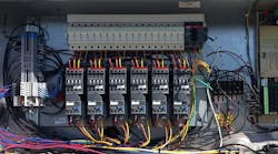
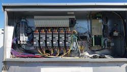
Often, a single VFD will be used for multiple motors, and a bypass mode control strategy for this application may use a single contactor for each motor (see Figures 1 and 2). The relative speed of each of the motors will be determined by the VFD’s volts and hertz (V/Hz) output. Since all the motors are connected to a single VFD, this V/Hz will be the same for each motor. Therefore, a VFD that is putting out 50% of the V/Hz will produce 50% of the base speed of each motor. So, it is important to realize that an 1800 rpm base speed motor will go approximately 900 rpm, but a 1200 rpm base speed motor will go about 600 rpm. In the event of a VFD failure, the system could be operated by a control system called “staging.” Using staging, a single motor or multiple units can be taken online or offline to help maintain the desired setpoint or operation. This may not be as productive as the variable speed provided by the VFD, but it is often better than not running at all. Keep in mind that careful planning is required to ensure that the motors are not cycled on and off too many times to avoid overheating and leading to premature failure.
Safety and control wiring considerations for Bypass contactors
Let’s look at some of the control wiring involved with Bypass contactors. Most VFDs will not tolerate line voltage to be applied back into its output, where sensitive transistors are located. For this reason, the VFD output contactor and the Bypass contactor must be wired and controlled to prevent this from happening. The most direct way to accomplish this is with electrically interlocked coils (see Figure 3). Using normally closed auxiliary contacts on each contactor, the control voltage for a specific contactor’s coil must run through the other contactor first. Thus, only an off or “out” contactor will provide a complete electrical path for the control voltage to reach the other contactor’s coil.
It should be noted that contactors from different manufacturers will turn on and off (also known as collapsing) at different rates. Although these times are in the millisecond range, an overlap where both contactors have closed contacts simultaneously could damage the output of the VFD. To prevent damage from different rates of collapse, only circuits from the same manufacturer and type of family or model should be used for these contactors.
An additional layer of protection is the use of mechanical interlocks. This option is typically a small mechanical device placed between mating contactors that physically prevents one contactor from turning on or pulling in, when the other is already engaged or has not dropped out yet. Most often, these two contactors are the VFD output contactor and the Bypass contactor. Since the output of both contactors leads to the motor(s), the output terminals are often linked together by jumper bars or wires. Thus, if both contactors are pulled in at the same time, even briefly, raw power will flow through the Bypass contactor, over to the VFD output contactor, and back into the VFD output. The mechanical interlock is designed to prevent this and provides another level of protection for the expensive VFD.
To bypass or not to bypass?
VFDs can do remarkable jobs at increasing production, improving efficiency, and saving energy. However, they are usually the first device that gets the blame if something goes wrong. Furthermore, if a system ran fine for years on a simple mechanical design consisting of contactors and on/off logic, sometimes adding a variable-speed electronic device may challenge the current machine operators.
The success of adding VFDs to these systems lies in incorporating the new with the old while anticipating how the two can be constantly improved for maximum safety and production. The previous use of contactors does not mean that they must be eliminated completely in the new design. They can be merged with the VFDs to continue to provide a functional bypass system that can be used when necessary. One of the best prevention strategies is to train the maintenance staff, including the operators, on proper device management and common fault modes. If your plant personnel are limited by time or scope, or hesitant to take on the challenge of designing and incorporating VFDs into your current systems, contact third-party integrators or automation engineers for assistance.


