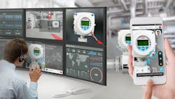
Automated condition monitoring is a game-changer for maintenance teams and asset managers, especially in industries such as chemicals and power generation where maximizing safety and optimizing uptime are critical considerations.
Condition monitoring is not a new idea, but barriers of cost, complexity, and scalability have previously prevented many more businesses from enjoying the promised benefits. However, over the past five years developments such as greater connectedness via Industry 4.0 and the Industrial Internet of Things (IIoT), artificial intelligence (AI), and machine learning have been clearing many of those barriers. IIoT is key because condition monitoring involves having access to a reliable stream of quality plant data that can be interrogated for the warning signs of impending failure. Meanwhile tools based on AI and machine learning can automate the data analytics required to spot those warning signs and interpret them for operators.
The reliance on instrumentation to deliver reliable data for condition monitoring raises an important question: In addition to using sensors to monitor associated assets, what steps should operators be taking to monitor the condition of the sensors themselves?
The role of instrumentation
Process instrumentation takes data from the production environment and passes it back to the condition monitoring solution. In many cases, the data is already being gathered for process control purposes. In other examples, additional instruments are installed specifically to provide data for condition monitoring purposes.
Various parameters provide useful information for condition monitoring. Vibration and temperature are among the most common, since they can be measured non-invasively and can point to a multitude of potential maintenance issues, such as bearing wear in rotating machinery. Motor current signature analysis (MCSA) is another common approach since a motor being used to drive worn or failing equipment will often draw power differently.
Regardless of what operators are measuring, there are two main approaches that can be used for condition monitoring: trend monitoring and condition checking. Trend monitoring is the continuous or regular measurement and interpretation of data. It involves choosing a suitable and measurable indication of machine or component deterioration and tracking changes in this measurement over time. The aim is to alert operators when deterioration exceeds a critical rate or absolute threshold.
Condition checking is more of a snapshot. It takes a check measurement of a suitable indicator with the machine running and uses the result as a measure of the machine condition at that moment.
Who monitors the monitors?
Instruments are the eyes and ears of any condition monitoring solution. If they are not working properly, they could be generating a distorted picture of what is happening. Even the smartest AI-based system cannot deliver the expected benefits if it is being fed with incorrect information.
Today’s process instruments are largely digitally based. As such they produce a wealth of information not just about the behavior of the parameters they are designed to measure, but also about their own performance and accuracy. Many modern devices can check their own circuitry, help with their own calibration, and evaluate their own performance.
Yet, these capabilities are not as widely used as they could be. Many operators are not using this available data to its full extent and are therefore missing out on advances in device diagnostics and maintenance. So how can measurement device users begin to take advantage of these capabilities?
Step 1: Leverage digital communications links. Put simply, it comes down to communication. Although most measurement devices are digital, many applications continue to use the tried and tested 4-20mA current loop, rather than digital communications networks.
Thankfully, this does not prevent instruments from providing a degree of self-diagnostics. For example, many 4-20mA measurement devices also offer HART communications, a bi-directional communication protocol that provides data access between intelligent field instruments and host systems. HART connections can provide some condition-related information, but that does not typically provide enough detailed diagnostic information to determine if the device has drifted away from the parameters set at the factory or during commissioning.
In contrast, modern digital communications links are able to reliably carry both process values (such as flow rates or temperature) and device diagnostics data (such as operational status). Many advanced digitally enabled measurement devices will offer sensor checks including internal connections, an indication of sensor memory failure and an internal electronics check.
Step 2: Interrogate the instruments. With communications in place, device interrogation is the next step. Many devices include inbuilt condition monitoring and diagnostics based on the NAMUR NE 107 standard. To make things easier for the personnel who need to deal with alarms, NAMUR NE 107 categorizes internal diagnostics into four standard status signals – failure, function check, out of specification, and maintenance required – each of which can also contain greater detail. For example, with a failure signal, can the failure be traced to the device, or is the process at fault? Devices with NAMUR NE 107 diagnostics built in allow plant teams to turn off diagnostics that are not required; these teams also can configure how the diagnostics are reported.
Step 3: Verify device accuracy. Field verification and calibration both enable plant teams to maintainin the accuracy of many condition monitoring devices. However, device calibration generally requires the removal of the device which is often costly and impractical within a plant that operates continuously.
Manual verification, performed by hand using multimeters and similar devices to check that the device circuitry is measuring as expected, also suffers from a number of drawbacks. As well as requiring longer downtimes, it also needs specially trained technicians. In addition, every time a person works on a device it creates another opportunity for human error, potentially resulting in further, unplanned downtime.
Software verification is faster, but it often means using different software packages for different types of devices because one type of verification software may not work with all devices from multiple suppliers or with the many different communications protocols.
Even so, some of the best modern verification software packages can be used for many device types, comparing their settings to when they were first commissioned or calibrated and determining if their performance has degraded in the meantime. These software packages can often perform a deep analysis of the device’s condition with no need for specially trained technicians. A report is produced on the calibration variables, assessing the limits and determining if the device has passed or failed on each one.
Widespread adoption
The decision about how far to go with condition monitoring is ultimately a matter of cost versus benefit. Where that decision falls for each plant team will depend on many factors, such as the criticality of equipment and the size of the facility, for example. However, thanks to the increasingly rich data sets now available as standard from digital instruments, adopting a condition monitoring approach to sensor networks is one area where the balance has largely tipped in favor of using digital diagnostics more widely.


