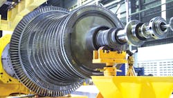
A steam turbine driver converts the thermal energy of steam into useful mechanical work to drive the equipment and machineries. Steam turbines can deliver constant or variable speed and are capable of close speed control. They serve as the drivers for pumps, compressors, fans, blowers, and many more.
Steam turbines have always been important parts of plants. As an indication, steam has supplied power to about 20-25% of all pumps, compressors, and machineries that moves fluids in plants.
Steam turbines are classified by mechanical arrangement, as single-casing, cross-compound (more than one shaft side by side), or multi-casing (tandem-compound), which is two or more casings in a single train. Steam turbines are also identified by steam flow direction, which is axial for most but radial for a few. Steam turbines can be categorized by steam cycle, whether condensing, non-condensing, automatic extraction, or reheat type.
In a steam turbine, the steam flow proceeds through directing devices and impinges on curved blades mounted along the periphery of the rotor. By exerting a force on the blades, the steam flow causes the steam turbine rotor to rotate.
The steam turbines proved to be very convenient drivers. They can be configured to operable at the speeds of driven equipment. They are more compact, lighter, better balanced, and more economical than the other drivers, such as reciprocating engines, gas turbines, or electric motor. Steam turbines has been substantially developed because of extensive use in the last 100 years. The efficiency has been significantly improved; output capacity has also been increased; and specialized steam turbines were provided for various driver applications.
This article discusses steam turbine drivers with the focus on operation, reliability, and maintenance.
Steam cycle and steam turbine driver
The cycle for the steam turbine driver consists of a heat source (boiler or heat recovery unit) that converts water to high pressure steam. In a steam cycle, water is first pumped to elevated pressure using boiler-feed water (BFW) pumps, which is medium to high pressure depending on the size of the unit and the temperature to which the steam is eventually heated. The steam is then heated to the boiling temperature and then most frequently superheated (heated to a temperature above that of boiling). The pressurized steam is expanded to lower pressure in a multistage steam turbine, then exhausted either to a condenser at vacuum conditions (condensing) or into an intermediate temperature steam distribution system (non-condensing) that delivers the steam to other applications. The condensate from the condenser or from the industrial steam utilization system is returned to the BFW pumps for continuation of the cycle.
The steam turbine driver itself usually consists of a stationary set of blades (called nozzles) and a moving set of adjacent blades (called buckets or rotor blades) installed within a casing. The two sets of blades work together such that the steam turns the shaft of the turbine driver and the connected driven equipment. The combination of torque and speed is the output power of the steam turbine driver.
Material selection and configuration
The evolution of the steam turbine drivers has always been coupled to advances made in high-strength steel alloys. Steam admission temperatures have continuously been improved battling severe restrictions in boiler and turbine operating flexibility. Old-fashioned alloy steels were used up to 550 °C. For 580 °C and beyond, modern alloy steels should be used. The creep has been an important consideration for high-temperature steam turbine drivers and proper super alloys are needed to keep creep deformation within acceptable limits.
In addition to temperatures, centrifugal forces put high stresses on rotor and blade materials. A high yield strength combined with good fracture toughness is an important requirement. However, these are metallurgical contradicting properties, making it difficult to increase them simultaneously. An important challenge becoming evident during the last four decades was the occurrence of some stress corrosion cracks (SCC) in highly stressed discs exposed to wet steam.
Many steam turbine rotor blades have shrouding at the top, which interlocks with that of adjacent blades, to increase damping and thereby reduce blade flutter. In large steam turbines, the shrouding is often complemented, especially in the long blades of a low-pressure turbine, with lacing wires. These wires pass through holes drilled in the blades at suitable distances from the blade root and are usually brazed to the blades at the point where they pass through. Lacing wires reduce blade flutter in the central part of the blades. The introduction of lacing wires substantially reduces the instances of blade failure in large or low-pressure turbines.
Part-load or off-rated conditions occur on many occasions in steam turbines, for instance, at start-up, shutdown, and at part-load operation, operation below the rated speed and rated load. Particular attention is required for part-load operation of steam turbines with regulated steam extraction system.
Steam turbine lubrication
Steam turbine lubrication oils are subjected to a wide range of conditions such as extreme heat, entrained air, moisture, contamination by dirt and debris, inadvertent mixing with different oil, and others; all these degrade the integrity of the lubrication oil base stock and deplete the additive chemistries, causing irreversible molecular changes. There are two primary degradation mechanisms in steam turbine applications—oxidation and thermal degradation.
The rate of oxidation depends on a number of factors. The temperature is perhaps the most critical one. As a rule of thumb, the rate of oxidation doubles for every rise of 10 °C. The temperature above which this occurs is influenced by the oxidation stability of the oil and the presence of catalysts and pro-oxidant conditions such as water, air, certain metals, fluid agitation and pressure. Thermal degradation is the breakdown of the oil molecules by heat (high temperature), forming insoluble compounds that frequently are referred to as soft contaminants.
The oxidation performances of the different base stock classes are quite different. The high natural oxidative resistance of some superior turbine oils combined with specific anti-oxidants employed provide a nonlinear behavior in terms of their molecular degradation over time. As a result, the majority of standard oil analysis tests offer little to no warning as the lubrication oil starts to degrade and generate deposits. Instead of degradation occurring in a linear and predictable fashion, many of the modern turbine oils fail rapidly.
Changes in the oil’s molecular structure due to additive depletion and the development of insoluble particulates are among the first oil degradation conditions that affect the performance of steam turbines. The sequential process will be the formation of sludge and varnish, which are common occurrences in steam turbines. Besides these, oxidation and thermal degradation by-products being the main contributors for the development of varnish and deposit problems in steam turbines. They interfere with other important properties in steam turbine lubrication oils, such as demulsibility and the detrainment of air. Appropriate diagnostic analysis should be performed to detect these at early stages.
Corrosion and erosion
Corrosion is the most common damage mechanism resulting from deposits in the steam turbines. Increased surface roughness acts to increase deposition. The periods of unprotected (non-protected) shutdowns, when the steam turbine is left unoperated and unprotected, play a major role in associated damages of corrosion.
Pitting and localized corrosion are unlikely to originate during steam turbine operation due to the absence of oxygen in the liquid films on the steam turbine surfaces during operation. Rather, pitting results from corrosive deposits absorbing moist air during steam turbine shutdown.
The “corrosion fatigue” (CF) and stress corrosion cracking of steam turbine components have been consistently identified among the main causes of steam turbine unavailability. Both phenomena are characterized by two stages: initiation and propagation.
In steam turbines, initiation most frequently occurs at micro-cracks that emanate from pits that form when deposits become corrosive during unprotected shutdowns. Cracks can, however, also initiate on locations of fretting, manufacturing defects, inclusions, microscopic imperfections, and others. Propagation of CF and SCC is driven by cyclic or steady stress situations.
Pitting and localized corrosion are important initial points for more extensive damages from stress corrosion cracks and corrosion fatigue, although extensive pitting of blades can cause significant loss of stage efficiency or, in extreme cases, weaken component integrity to the point of failure.
During non-protected shutdowns where the blade and disk surfaces are open to the atmosphere, any deposits, particularly chloride or sulphate, which have formed on steam-path surfaces during operation can become moist and lead to local, conductive, aqueous environments that contain ppm levels of oxygen. These local environments initially lead to breakdown of the blade metal passivity, then to metastable pit formation, and finally to stable pits after repeated shutdown cycles.
Each shutdown period is followed by operation where the dynamic situation of droplet formation, liquid films, and deposition occur. Once a steam turbine has resumed operation, liquid films can re-passivate areas where passivity was lost during shutdown and metastable pits had formed. However, deposition continues to occur during operation, and deposits associated with a loss of passivity that caused a metastable pit during one unprotected shutdown will lead to further growth of that pit during the next (extended) unprotected shutdown. Repetition of this process will eventually lead to a stable pit. Too often, these pits are not visible, but because they have resulted from an active corrosion mechanism during shutdown the internal surfaces will be rather irregular. Therefore, the different environments which exist during the repetitive operation and shutdown periods eventually lead to the initiation and growth of a number of pits on the surface.
Steam turbine components may also be attacked by flow-accelerated corrosion (FAC) when liquid films form on steam turbine components in the presence of two-phase wet steam. Poor steam purity can cause low pH in such films, and thus trigger or enhance FAC. The use of suitable alloys (such as Cr-alloyed steels) can mitigate and even prevent FAC.
Particle erosion is another significant operational problem in steam turbines. The liquid erosion is commonly reported, particularly for saturated steam and condensing steam turbines. Solid particle erosion is commonly caused by iron oxide particles that scour the surface of blades, mainly in the initial stages of each steam turbine casing. The source of such particles is oxide on super-heater and re-heater tubes and piping that exfoliates during transient operation such as start-up and shutdown.
Steam turbine market
The number of steam turbine manufacturers in the world has been declining over last 40 years. The logical “few per nation” rule that was popular three or four decades ago has given place to the more modern “few per continent” rule. Different manufacturers merged and technical co-operation have amalgamated technological elements of very different philosophies within a single turbine manufacturer. Competing concepts and configurations can now be compared and critically evaluated before being offered to the market. These changes lead to a sharper selection of development concepts, but also to more flexible answers to market needs.
Steam turbine engineering and manufacturing are embedded in a changing world. Advances made in materials science, mechanical, or others may strongly affect steam turbine technology and operation. The same holds true for controls, data processing, manufacturing technologies, production, reliability, maintenance and operating procedures, and many other domains.
This story originally appeared in the July 2021 issue of Plant Services. Subscribe to Plant Services here.
Amin Almasi is a machinery/mechanical consultant in Australia. He is chartered professional engineer of Engineers Australia (MIEAust CPEng – Mechanical) and IMechE (CEng MIMechE) in addition to a M.Sc. and B.Sc. in mechanical engineering and RPEQ (Registered Professional Engineer in Queensland). He specializes in mechanical equipment and machineries including centrifugal, screw and reciprocating compressors, gas turbines, steam turbines, engines, pumps, condition monitoring, reliability, as well as fire protection, power generation, water treatment, material handling and others. Almasi is an active member of Engineers Australia, IMechE, ASME, and SPE. He has authored more than 200 papers and articles dealing with rotating equipment, condition monitoring, maintenance, condition monitoring, fire protection, power generation, water treatment, material handling and reliability. Contact him at [email protected].

