Roofs protect our property, processes and products from the elements.
While roof structure failure is fairly rare, roof membrane failure, however, is not. The consequences of roof leaks range from nuisance to economic devastation. Aside from cleanup and roof repair, the costs include damage to equipment and processes, loss of productivity and destruction of product.
Causes of roof leaks can be subtle and difficult to pinpoint. Obvious causes may be embrittlement and cracking of aging roofing material and atmospheric and environmental degradation. Weather-related damage is also fairly easy to recognize. Other failures may be service related — either lack of routine service (clearing debris, leaves, etc.,) or as a result of service, such as a mishap during rooftop equipment repair. These are often harder to locate, isolate and repair.
Roofing systems
Roofing systems have evolved through the years, driven by building technology, size and function. Steeply pitched roofs are ideal for long life in a varied environment. They drain water almost immediately and shed snow and ice with little effort. However, geometry and economics limit their usefulness for covering large areas such as industrial buildings.
Industrial buildings need large, open spaces, which requires large roof areas. Because of this scale, industrial buildings have “flat” roofs. Flat roofs actually slope from 0.5 inches to 0.25 inches per foot. Slope depends on environmental conditions, roof system construction or other roof functions besides weather protection. In most cases, unless the roof is intended to store it, the goal is to move water off as quickly as possible.
Broadly speaking, the great majority of industrial buildings use either a plasticized or rubberized membrane roofing system, or a built-up system with multiple layers of mopped hot bitumin. Each system has merits and limitations, but for this discussion, there is no distinction to be made here.
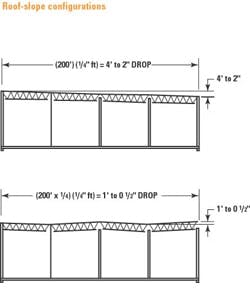
Roof slope can have a considerable impact on the building’s structure. A roof sloped uniformly at 0.25 inches per foot will drop more than four feet across a 200-foot length. Longer runs and steeper slopes increase the elevation change and can greatly impact the available interior space. One common method to reduce the impact is to slope and counterslope the roof (see Figure 1).
Another factor influencing slope is the need for secondary drainage. Current building codes require that roof construction not allow water to accumulate to a depth that could result in structural failure. For example, water can become trapped by the saw-tooth roof arrangement, by a parapet or by adjacent buildings. When this occurs, a secondary drainage system or relief must be provided.
External drainage systems
External drainage systems are divided into two types: an external gutter with a downspout or a scupper with a conductor head and downspout.
External gutter and downspout
This is the lowest cost and easiest method of roof drainage available. It is characteristically a sheet metal gutter that is fastened to the building face or fascia after construction is completed. The roof edge detail is usually a gravel stop with drip-edge flashing and counterflashing. The lightweight construction makes it a good choice for smaller roof areas not susceptible to damage by vehicles or equipment. The relatively small gutter cross-sectional area limits the amount of roof that can be served. This system normally does not require secondary drainage. Typical materials of construction are aluminum, stainless steel and galvanized, steel-edge flashing, gutters and downspouts.
Scupper with conductor head and external downspout
A scupper with conductor head and an external downspout offers a higher level of performance and costs more than an external gutter system. Scuppers are used where a building has a parapet raised at the roof edge. Water flowing over the wier falls through air into the conductor head. The components consist of a scupper box with flashing and counterflashing, a conductor head, and downspout. The scupper size is based on the rainfall rate, roof area and discharge capacity.
The conductor head is a large, box-shaped receiver that collects water from the scupper and routes it to the downspout. The downspouts are usually round or rectangular. Secondary drainage must be considered, but often this is included in the capacity of the primary scupper. Because the junction between roof and parapet must be properly flashed and counterflashed, this design receives greater scrutiny and detailing by design professionals and contractors. This additional attention often includes details of mounting locations and techniques for the conductor head and downspout. This system is reliable and appropriate for large roof areas. Typical materials of construction are stainless steel, copper or galvanized steel.
Internal drainage systems — roof drains
Roof drains with interior rainwater piping are often the highest cost method for draining roofs. However, it offers the greatest flexibility in roofing design. Roof slopes can be developed as needed and drains are installed at low points and sized to suit the drainage area and rainfall rate. Roof drains are installed as an integral part of the roofing assembly and must be compatible with roof structure, insulation and waterproofing membranes. Many commercially available roof drains meet these requirements and are standard products with standard options. Because of the standardized nature of these products, many contractors, and some design professionals, sometimes overlook the details of the drain and roof assembly. This often leads to premature failure (leaks) and unhappy owners.
Here are some key details to remember when designing a roof drainage system.
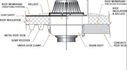
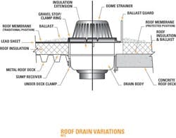
On corrugated metal decks, a sump receiver plate should always be used to distribute the weight of the drain uniformly.
Unless cast into a concrete deck, roof drains should have underdeck clamps. This secures the drain body to the structure, making it integral to the roof structure. Without this clamp, the drain body will move independently from the roof assembly, causing stress at the interface with the roofing membrane.
Appropriate extensions should be provided if the insulation is located on the top of the roof deck. Often, insulation is shaved or tapered in an attempt to avoid an insulation extension. However, this is not recommended by either drain or roofing system manufacturers.
[pullquote]The joint between the roofing membrane and the drain body is critical. It’s made by fastening the gravel guard to the drain body and clamping the roof membrane between the two pieces. To provide support for the membrane, most engineers will specify a lead sheet to extend 12 to 18 in. from the clamp ring and below the roofing material. This small detail can greatly improve the junction’s effective life.
Strainers are required by code and should typically be the dome type. They should be secured to the drain to prevent being blown away (or otherwise removed). The size of roof ballast also should be coordinated. If too small, it passes through the dome strainer, leading to possible stoppage problems.
Drain piping should allow for movement. The temperature differentials produced when cold rain hits a warm building cause considerable movement in the piping system. Elbow offsets usually compensate for this movement; however, if the drain piping runs straight down from the drain connection to a fixed point, an expansion joint probably will be necessary.
Horizontal rainwater piping in humid, heated areas should be insulated to prevent condensation and potential water damage. The same holds true for the underside of the drain body.
Secondary drainage, such as scupper or secondary roof drains, will be required. Secondary roof drains are similar to primary drains except they have wiers or standpipes that elevate the inlet above the level of the primary drains. Secondary drainage piping must be separated from primary piping and must discharge at an observable above grade location.
Materials for roof drains are usually cast iron or plastic, but may be cast bronze or even stainless steel. Common piping materials include PVC, cast and ductile iron, and galvanized steel.
Piped roof-drainage systems require additional coordination and attention to details for proper installation. However, they allow great flexibility in roofing design, are pre-engineered to allow for easy installation and repeatability, and are reusable when the roofing material must be repaired or replaced.
Selection of a roof drainage system is important to your building’s long-term success. Initial costs may be a limiting factor in system selection, but they should not be the only consideration. A higher priced system may be a better value. Regardless of the system selected, success will come from attention to details, proper installation, and timely and routine roof and drainage system inspection.
Connelly is a consulting engineer for Newcomb & Boyd. He can be reached at (404) 352-6662 or via email at [email protected].


