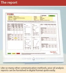
Lubricants are the lifeblood of industrial machinery. They protect critical components and help promote enhanced operation, just as blood supports health in the human body. And, while a doctor learns valuable information about a patient’s health through a blood test, you can garner valuable insights about your equipment using routine oil analyses.
Oil analysis is based on a slate of tests designed to help evaluate the condition of internal hardware as well as the in-service lubricant. With this information, you can extend the useful lives of both, by identifying early warning signs such as contamination or increasing wear metals which will allowing you to minimize unscheduled maintenance.
Below are some of the basics of oil analysis for the standard industrial applications: hydraulic systems, compressors and gearboxes. Using these tips as part of your proactive maintenance program will enhance your equipment's performance and boost productivity.
Take a representative sample
You must follow a certain protocol to ensure the accuracy and to gain the most benefit from your oil analysis results. First, always use a clean, dry container to draw oil samples. Store sample bottles in a clean dry, dust free area until the sample is taken.
Draw samples when equipment is at its normal operating temperature and while the machine is running, if it can be done safely. Otherwise, it is recommended to draw samples as soon as possible after the equipment has been shutdown.
A properly placed sampling valve complements an effective engineered analysis program. Ideally, take samples downstream of the filters, as it will most represent the condition of the oil that is supplying the critical lubrication points. To find the ideal sample point, review the equipment’s lubricating system. Normally, compressors and gearboxes are splash lubricated bath type reservoirs/sumps and hydraulic systems usually have circulation systems with a central reservoir housing the bulk of the oil.
The optimum sampling method for a circulation system uses a sampling valve or spigot at a high flow point just down stream of the filtration equipment. If this point is not available, take samples from either the main return line or secondary points that are safely accessible.
When sampling through a fixed valve:
- Remove the valve protective cap
- Open the valve and drain about four ounces of oil through the valve into a slop bucket to flush any stagnant oil or contaminants that might have settled in the valve. Don’t close the valve.
- Remove the sample bottle lid and avoid introducing any environmental atmospheric or surface contamination.
- Collect your oil sample, filling the bottle only to the shoulder, leaving room for expansion and contraction.
If your analysis slate includes particle counts and you’re using standard production sample bottles instead of the “super-clean” variety, follow steps 4a through 4c to obtain the most representable sample.
4a. Dump the oil sample into the slop bucket to flush and remove any inherent bottle contaminants. Don’t close the valve.
4b. Collect another oil sample and discard it, too.
4c. Collect your final oil sample, filling the bottle only to the shoulder.
5. Replace the sample bottle lid.
6. Close the sampling valve.
7. Replace the protective cap on the valve.
8. Fill out the sample label and attach it to the bottle.
9. Record any unusual operating conditions (noise, leaks, temperature, vibration, etc.).
Avoid sampling from reservoirs where possible as stratification and sediment can produce unrepresentative samples that will adversely skew the results. If the equipment doesn’t have a circulating system, which is the case for some gearboxes, take samples from the gearbox bath or sump. Insure that samples are taken several inches from the bottom of the bath, to avoid accidentally including the insolubles/sludge layer that has appropriately settled to the bottom.
If you have any question about the most appropriate sample point, consult the machine manufacturer for advice. Once the optimum sampling location has been identified, note it in the maintenance records. This ensures that future test results will provide the most accurate trend line and level of insight.
Viscosity can be a variable
Viscosity is a measurement of a lubricant’s resistance to flow. This variable or characteristic is the most critical parameter for most applications and can change over time or more quickly in equipment that sees extreme temperatures or high pressures or high speeds. Always monitor lubricant viscosity closely, to ensure that it is within the targeted viscosity range which will minimize wear between critical equipment components. Some typical ISO viscosity grades for various industrial applications include:
- Hydraulic systems: typically around ISO-46 to 68 but can range from ISO 32 to 220 based on service type where temperature, speed or load demands can vary.
- Gearbox: typically around ISO-220 to 320 but can range from ISO 150 to 1000 based on service type where temperature, speed and load demands can vary.
- Air compressors: most typical is ISO-46/68 but can range from ISO 32 to 150 based on temperature, speed and load demands can vary.
If the viscosity changes by +/-15% of its original value, monitor the oil more frequently. Equipment can perform normally if the lube is outside of this range, but it should be watched more closely as this usually indicates changes are needed. All equipment applications have stated recommended operating temperatures and recommended lubricants that meet that condition. If oil temperatures significantly vary (particularly trending higher) it is recommended to re-review the ISO grade of the oil to ensure that an appropriate film thickness is being provided to insure efficient wear-free performance.
Lubricant manufacturers devote substantial resources to formulating lubes that are robust enough to perform with altered viscosity. It’s important to have faith in your oil, but you should set a logical sampling schedule to monitor changes and specifically changes in viscosity. Every month is often the recommended interval for sampling on critical or costly equipment.
Track wear metals
Monitoring wear metals is important for tracking equipment health. As equipment ages, components start to wear, and so it’s important to monitor the degree of wear to permit scheduling routine, planned repairs rather than waiting for unplanned equipment shutdown. Common wear metals to be monitored for various systems include:
- Hydraulics: copper, iron, lead (aluminum, tin, chromium less common)
- Compressors: iron, copper, lead (tin, aluminum, nickel less common)
- Gearboxes: iron, copper, aluminum (lead, tin, chromium less common)
Iron and copper are used in nearly every piece of equipment, so monitor their presence closely for the three machine types. Don’t be overly alarmed if elevated levels of iron or copper appear in the oil analyses at the beginning of the lube’s service life as that is typical during the "break in" period for new equipment.
Bearings generally contain copper along with various alloys (i.e. like lead aluminum, chromium or tin) and have a limited life and will eventually wear out. You just don't want them to wear out too fast. This is where you can get a lot of value from your analysis reports. You might see a spike in iron concentration when the equipment is brand new. For example the surface topography of a gear profile will wear down until it smoothes out and further iron wear subsides.
Sometimes, the copper concentration can rise from about 20 ppm and then levels off to a consistent 50 ppm with out going any higher. If copper levels continue to increase, the gears might be overloaded or out of alignment, causing unusually high bearing wear and will need attention (realignment or replacement). Worm gears which are composed of bronze (a copper/tin alloy) will see very high copper levels 500 to 1000 ppm due to the normal wear of the sacrificial/softer bronze worm gear. Additionally, high levels of copper wear metals in used oils can act as a catalyst that can further accelerate the oxidation/break down of the oil.
Manufacturers differentiate themselves by engineering unique metallurgy into their equipment. For example, various levels of aluminum and lead are used in the production of bearings for compressors and gearboxes. Bearing metals are critical and should be monitored closely because they can give you an early indication if something is going wrong. Consult the OEM to determine if there are any unique metals used in their equipment that should be monitored with oil analysis.
Oil analysis on gearboxes can show much higher levels of iron and still be considered normal because gear teeth are going to wear. So, levels exceeding 200 ppm should be monitored more closely. However, iron levels in compressors and hydraulic systems will be lower and are considered normal if they are 40 ppm or less.
Contamination kills
Contamination is among the most common causes of equipment shutdowns and can come in different forms: dirt, dust (airborne particles) or water being the most common. Most airborne contaminants show up in an oil analysis as silicon.
The typical silicon concentration for industrial equipment ranges from 5 ppm to around 20 ppm, as most lubricants are formulated to contain a silicon defoamant that reduces the chances of the oil foaming while in use. Anything above 50 ppm should be looked into more closely as it is most often due to intrusive contamination of abrasive silicon.
While it’s an expensive fix, foreign silicon can be prevented or mitigated with the appropriate application of filters and air breathers.
The most effective way to extend equipment and lubricant life is to implement a comprehensive oil analysis program. It will help identify early warning signs of contamination and minimize unscheduled maintenance.
George B. Mullins is the Global Signum Oil Analysis Program Technical Adviser at ExxonMobil Lubricants and Specialties in Fairfax, Virginia. E-mail him at [email protected].

