When plant equipment operates at its design capacity, it’s ready for prime time reliability. If the equipment can’t, then it’s past time that you did something about reliably maintaining the promised production rates.
Almost all machinery is designed to some set of industry standards, but many purchasers don’t really understand what they bought. Sometimes the vendor responds to a question about expected machine life and rated performance with a statement such as, “It was designed to the XYZ Institute standards.” The purchaser then nods knowingly in an attempt to appear that they fully understand what the vendor implies. But both of them don’t realize that the performance requirements are apples and institute standards are oranges.
Some purchasers, on the other hand, either don’t know what questions to ask or don’t specify any particular life criteria in the equipment RFQ, as was the case for two of our projects. In the first, some machine components at a pharmaceutical plant needed to cycle about 100 times per month. For the first few years, the entire machine functioned well. Then, a pattern developed of frequent, expensive component failures, with even more costly production interruptions. When asked about the component design life, the vendor stated it was 3,600 cycles, about three years at the current cycling rate. The items involved in these failures certainly were not consumables. In our opinion, nothing in an industrial plant, other than wear items such as belts and chains, should be designed to fail in only three years.
In the second case, a client bought several conveyor drives for a processing plant. Three years after installation, the first shaft-mounted reducer failed. Two months later, a second failed. Our detailed failure analysis revealed that the operating conditions and the initial specified conditions were almost identical. The problem, it turned out, was an attempt to save on the initial expenditure. The client specified the unit with a service factor that almost guaranteed it wouldn’t last much more than three years.
Everyone is familiar with the saying “A chain is only as strong as its weakest link.” The key to equipment life lies in the reliability of the individual components. If they’re not chosen and maintained properly, the machine in which they’re installed won’t be available when it’s needed.
Expected lives
Most complex machines, such as motors, pumps and reducers, are designed around the L10 life of the rolling-element bearings. The L10 life identifies the time interval when 10% of the population is expected to fail. We’ve all seen the bell curve showing the distribution of bearing failures over time and, in most cases, the average bearing life, the L50, is about 4.5 times the L10.
L10 life is inversely proportional to the cube of the load. What many plant professionals can’t seem to grasp is that increasing the bearing load by only 10% reduces the fatigue life by about one-third. When asked if they understand the relationship between load and bearing life, they will say yes and act as though they can’t understand why one would ask such a simple question. But, a casual walk-around inspection of the plant reveals that plant personnel don’t truly understand basic mechanics. You’ll see sheaves and sprockets mounted at the very ends of motor and reducer shafts, a configuration that maximizes bearing loads and slowly eats away at the machine reliability.
Your job involves dealing with individual mechanical components such as belts, chains, sheaves, sprockets, gears, seals and couplings. Knowing their expected lives and the possible consequences of your actions on their performance and reliability will help you make more intelligent decisions regarding both purchasing and maintaining machinery.
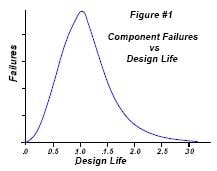
With the complexity of common electromechanical machines and the variables to which they’re exposed during operation, it’s almost unheard of that a group of end-of-life failures will occur during a narrow time span. Rather, the typical distribution looks more like Figure 1. Regardless of the calculated design life, some components will fail in much less time than the design suggests, the peak failure frequency generally occurs at or slightly beyond the design life, and the overall average life is greater than the design life.
Figure 1: Frequency of component failure as a function of design life
This distribution arises only when the components are operated according to established specifications. Deviations from standards can degrade machine life and shift the curve to the left.
V-belts
As V-belts operate, their polyester tension members slowly stretch, sometimes elongating by more than 1.5%. In addition, the sheaves and the belt slowly wear. That’s why belts must be retensioned. Plants that don’t inspect and adjust V-belt tension are limiting belt life to something in the order of 8,000 hours.
The Rubber Manufacturers Association (RMA) standard for V-belts states that drive life, when everything is run according to the book, should be 25,000 hours. This expectation assumes that the drive is properly sized, aligned and tensioned properly upon installation. It assumes that belt tension is adjusted shortly after startup (typically within the first 24 hours, or a million or so cycles). It assumes additional retensioning before slip reaches 5%. It’s based on a well-ventilated belt with sheaves in good condition. Failing to take any of these measures reduces the belt life.
- Studies by Gates Rubber have shown that, at temperatures higher than about 90°F, increasing the ambient temperature by 36°F cuts belt life in half.
- As sheaves become worn, the tension needed to drive them without excessive slip increases. A badly worn sheave can cut belt life in half while increasing both the bearing loads and the energy consumption.
- Increasing the load on a belt above its design load drastically cuts the life. A rule of thumb is that a 10% increase in load reduces belt life by more than 30%.
Synchronous belts
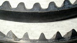
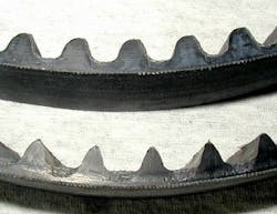
These drive elements don’t have to be retensioned because they exhibit less than 0.1% elongation in operation. But the “book” design life for these belt drives is about 12,000 hours. This assumes the operating conditions, such as properly aligned sprockets and clean and dry operating conditions, are ideal. The belt shown in Figure 2, on the other hand, lasted only six months because it was operated where abrasive dust was present.
Figure 2: This belt lasted only six months when it was operated in a dusty environment.
If you need a synchronous belt to last as long as a V-belt designed to the same standards, add 0.4 to your design service factor. In addition, most synchronous belt designs are sensitive to sprocket support rigidity. Deflections or misalignment that would have almost no effect on a V-belt can cause substantial life reductions in a synchronous belt. Switching from one type of belt to another always involves performance trade-offs. Book designs don’t allow for reverse bending with either belt type because it greatly increases the tension member fatigue stress, which shortens belt life.
Chain drives
Chain drives designed according to the book and properly maintained should last 15,000 hours. A key point is that chains are sensitive to lubrication and the allowable design loads vary with the lubrication method.
The moving components of a roller chain are case hardened to about HRc 50-plus. As the chain wears, hardened particles flake off and act like a lapping compound. Chain manufacturers’ studies show a chain’s life can vary by a factor of 1,000, depending on the lubrication method. This is because the bath and spray lubrication systems both remove the wear particles and resupply the additives critical to maintaining sliding motion. If the design lubrication conditions aren’t present, the lapping compound rapidly destroys the chain.
The bad news is that you must compensate for the stretch resulting from unavoidable chain drive wear by periodically adjusting the chain. The good news is that this slow growth can be used to predict when the chain needs to be replaced.
Couplings
It seems like grid and gear couplings have been used in industrial equipment forever. And with decent alignment and periodic relubrication, they can last almost forever in most applications. Gear couplings require such attention every three years; grid couplings, every five years. But couplings are sensitive to misalignment. The relative motion of the pieces consumes the grease additives that provide the protective films at the contact points. If the installation isn’t well aligned and the coupling isn’t properly lubricated, it may have to be disassembled, cleaned and relubricated annually.
Common alternatives to the older all-metal designs are units that use flexible elastomer inserts to compensate for misalignment. These units generally have lives between five and eight years, but they also have drawbacks. Some are sensitive to sizing, some are sensitive to even moderately elevated temperatures, and others are affected by the operating atmosphere. Understanding the design criteria for the specific coupling is a key to the unit’s reliability. The unit shown in Figure 3 fractured as a result of long-term (months) torsional resonance.
Figure 3: Torsional resonance destroyed this coupling in a matter of months.
Shaft seals
These are the weakest link in many of our applications. A seal failure allows fine dust and water to contaminate the lubricant, increasing the fatigue stresses and reducing bearing and gear life. Typical lip seal life is about 8,000 hours and, as with any elastomeric component, is dependent on ambient conditions.
Seal manufacturers are developing two-piece lip seals that are expected to last about 20,000 hours and some dynamic seals from several manufacturers will last many years.
The downside to these dynamic seals is that they cost much more than the simple lip seals, but they can help equipment like motors, pumps and reducers last twice as long. The key point is that most equipment is still furnished with essentially the same seals that were in use 30 years ago while reliability demands have tremendously increased.
Both the design engineer and the purchaser should understand how the pieces fit together.
There’s always a tendency to want to keep capital costs down. In some cases, that makes sense. But when that decision is made, recognize the potential long-term costs. This caution applies to setting up new facilities as well as upgrading existing equipment.
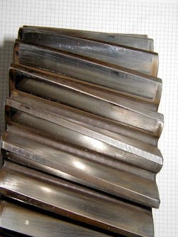
The case-hardened teeth shown in Figure 4 are from a gear in a reducer. A careful inspection of the photo shows pitting at the bottom of the dedendum, a warning of an impending disaster. The reducer was overloaded because the plant increased the operating loads without understanding the possible consequences. Fortunately, the damage was found before the reducer failed catastrophically. Don’t be like the plant managers who made this decision. When we asked them how their decision to increase production rates could affect equipment reliability, they had no ready answer.
Figure 4: Pitting at the bottom of the dedendum warns of upcoming gear failure.
Neville Sachs is CEO of Sachs, Salvaterra & Associates Inc., Syracuse, N.Y. Contact him at [email protected].


